Lake Shore Model 647 Magnet Power Supply User’s Manual
Table of Contents
iii
Chapter/Paragraph Title
Page
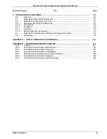
6 OPTIONS
AND
ACCESSORIES .................................................................................................... 6-1
6.0
General............................................................................................................................ 6-1
6.1
Model 6224 IEEE-488/Serial Interface............................................................................
6-1
6.2
Model 6476 Gaussmeter Input Card...............................................................................
6-1
6.2.1
Hall Sensor Mounting Considerations ............................................................................ 6-1
6.2.2 Connections .................................................................................................................... 6-2
6.2.3 Installation ....................................................................................................................... 6-2
6.2.4 Operation......................................................................................................................... 6-3
6.2.5 Remote
Operation Commands .......................................................................................
6-3
6.3
Model 6477 High Resolution Display and Programming Option .................................... 6-4
6.4
Accessories..................................................................................................................... 6-5
APPENDIX A – UNITS FOR MAGNETIC PROPERTIES................................................................... A-1
APPENDIX B – MAINFRAME REMOTE OPERATION ...................................................................... B-1
B1.0 General............................................................................................................................ B-1
B2.0
Control Bus Serial Interface Specifications..................................................................... B-1
B3.0
Control Bus Serial Interface Connector .......................................................................... B-1
B4.0
Control Bus Serial Interface Configuration ..................................................................... B-2
B5.0
Selecting the Control Bus Serial Interface Address........................................................ B-2
B6.0
Control Bus Serial Interface Operation ........................................................................... B-3
B7.0
Control Bus Serial Interface Sample Program................................................................ B-4


