background image

Lake Shore Model 647 Magnet Power Supply User’s Manual


Introduction


1-5

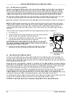
1.3.2  Low Noise, High Stability Current Regulated Output 
 Model 647 MPS:

 Maintains a high-stability 

low-noise current-regulated output. Digital 
setting and monitoring electronics, and 
computer interfacing integrate into power 
management and precision analog control 
circuitry. This integration maintains high 
output stability and repeatability. Extensive 
output filtering and noise cancellation 
circuitry keep MPS output noise very low. 
The MPS front panel graphic display allows 
continuous display of output current and 
voltage while setting parameters from the 
menu-driven keypad. In addition to the front 
panel and remote interface programming, 
the MPS includes analog inputs and outputs 
for setting and monitoring operating 
parameters and requires only 7 inches of 
rack space. 

Other conventional MPS's:

 Some use a 

compliance limited output with current 

monitoring to charge the magnet. Others 

require output current to drive against the 

output current limit to prevent output current 

drift. Most use multi-turn potentiometers and 

digital (or analog) panel meters for front panel current and compliance voltage setting. The elegance and 

repeatability of keypad entry is not available. There is no digital setting or monitoring integration in the output 

control circuitry. Most  achieve computer interfacing by adding computer controlled voltage sources to analog 

program the output current and voltage. Additional inputs must be added to digitize the output current and 

voltage. Setting and monitoring resolution is one to two orders of magnitude poorer than the standard MPS 

provides. External setting and monitoring complicates cabling. Degradation of the output current stability due 

to the addition of external cabling is undefined. Output noise specifications are rarely given and sometimes 

vary with the type of magnet load driven. These multiple unit configurations require up to 36 inches of rack 

space. 

1.3.3  Highly Efficient, Air Cooled, Compact Unit 
Model 647 MPS:

 Quiet switched-mode design. The output uses a proprietary pulse width modulated 

technique that incorporates power hybrid circuitry. Extremely low conduction loss components minimize 

internal power dissipation. The MPS is not a direct off-line switching supply. The output is fully floating and 

isolated from ground. Active power factor correction draws a sinusoidal AC current waveform from the utility, 

minimizes AC line harmonics, and lowers AC current required. Power factor is the ratio of real power 

(measured in watts) to the apparent power (measured in volt-amperes). The combination of quiet switched-

mode design and active power factor correction results in a compact, highly efficient, air-cooled unit. 

Other conventional MPS's:

 Most use linear regulated outputs. The output transistor pass-bank internally 

dissipates power not delivered to the magnet. Some units use an off-line switching supply to provide the bulk 

power and add output regulation. There is no input power factor correction. Low overall efficiency means 

higher input power and current. Without power factor correction, a non-sinusoidal current with high peaks 

places tremendous stress on fuses, circuit breakers, outlets, and wiring. Dedicated lines may be required 

because of potential interaction with other equipment. These factors result in low overall efficiency, large size, 

and considerable weight. 

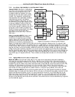
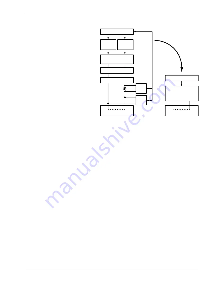
Magnet Load

Analog

Current

Programmer

Analog Programmed

Power Supply

Current Reversal

Energy Absorber

Analog

Voltage

Programmer

Computer

DVM

Current

Monitor

DVM

Voltage

Monitor

Magnet Load

Lake Shore MPS

True, Four-Quadrant

Bi-Directional

Power Flow

Computer

Now

Replaced

by:


Figure 1-2

 Comparison of Old and New MPS Designs


Содержание 647

Страница 1: ...d herein have been developed solely on company funds of Lake Shore Cryotronics Inc No government or other contractual support or relationship whatsoever has existed which in any way affects or mitigat...

Страница 2: ...nstalled in the United States or Internationally through our approved distribution agents This same protection will extend to any subsequent owner during the warranty period It does not apply to damag...

Страница 3: ...ower Flow 1 4 1 3 2 Low Noise High Stability Current Regulated Output 1 5 1 3 3 Highly Efficient Air Cooled Compact Unit 1 5 2 INITIAL SETUP AND CONNECTIONS 2 1 2 1 Inspecting and Unpacking 2 1 2 2 MP...

Страница 4: ...t Status Registers 4 4 4 1 4 Example IEEE Setup and Program 4 4 4 1 4 1 GPIB Board Installation 4 4 4 1 4 2 Run the Example QuickBasic Program 4 5 4 1 5 Notes On Using the IEEE Interface 4 5 4 2 Seria...

Страница 5: ...6 3 6 2 5 Remote Operation Commands 6 3 6 3 Model 6477 High Resolution Display and Programming Option 6 4 6 4 Accessories 6 5 APPENDIX A UNITS FOR MAGNETIC PROPERTIES A 1 APPENDIX B MAINFRAME REMOTE...

Страница 6: ...y Wiring 5 7 5 5 Model 2002 RJ 11 to DB 9 Adapter Wiring 5 7 5 6 Model 2003 RJ 11 to DB 25 Adapter Wiring 5 7 LIST OF TABLES Table No Title Page 1 1 Model 647 DC Output Specifications 1 3 2 1 MPS Line...

Страница 7: ...ple warnings cautions or notes are bulleted WARNING An operation or maintenance procedure which if not strictly observed may result in injury death or long term health hazards to personnel CAUTION An...

Страница 8: ...lace unit on a grounded conductive work surface 3 Ground technician through a conductive wrist strap or other device using 1 M series resistor to protect operator 4 Ground any tools such as soldering...

Страница 9: ...proper emergency measures such as electrical power shut off fire department notification fire extinguishing and personnel and records evacuation Here is a list of suggested personnel safety considerat...

Страница 10: ...covers Refer component replacement and internal adjustments to qualified maintenance personnel Do not replace components with power cable connected To avoid injuries always disconnect power and discha...

Страница 11: ...rsal is smooth and continuous with excellent near zero current performance Remote and local sensing of the output voltage Compensates for voltage drops in the output leads Quiet switched mode design R...

Страница 12: ...tion until load is discharged or utility is restored Utility High Line Turns off input and maintains operation until load is discharged Overvoltage Crowbars output when output terminal voltage induced...

Страница 13: ...1 mA 1 mV 1 mV Electronic Accuracy 0 1 IMAX 0 1 VMAX Display Resolution Standard High 10 mA 1 mA 10 mV 1 mV Stability Drift at 25 1 C Percent of full scale output change over 8 hours under constant l...

Страница 14: ...nventional MPS s Consist of a unipolar power supply with an energy absorber to dissipate magnet energy during discharge The energy absorber prevents reverse voltage generated during the discharge from...

Страница 15: ...ition of external cabling is undefined Output noise specifications are rarely given and sometimes vary with the type of magnet load driven These multiple unit configurations require up to 36 inches of...

Страница 16: ...Lake Shore Model 647 Magnet Power Supply User s Manual Introduction 1 6 This Page Intentionally Left Blank...

Страница 17: ...Warranty on the A Page immediately behind the title page 2 2 MPS MOUNTING After unpacking the MPS and verifying receipt of all packing list items mount the instrument in a suitable location The MPS s...

Страница 18: ...made EMI includes fixed and mobile transmitters high voltage power lines power tools and appliances florescent lights and other equipment containing motors heaters etc Protect the AC source from EMI...

Страница 19: ...e MPS is connected to the AC line and the MPS power switch is ON Initially the entire display clears and the alarm sounds for a short time The MPS initializes itself and displays the model identificat...

Страница 20: ...e alerts other system components of the fault In an auto parallel system up to four MPS units connected in parallel these signals connect in parallel between each of the MPS units See Paragraph 2 6 fo...

Страница 21: ...ND m produces 100 A V Voltage may come from a voltage source or from the center tap of a potentiometer connected from Is to Is 16 Is Positive voltage supply for programming external current with a pot...

Страница 22: ...ION Maintain polarity between S and OUT and S and OUT The S and S inputs control the output voltage Improper polarity may apply damaging voltages to the load 4 Connect the ground shield to the mountin...

Страница 23: ...nt distance from each other Replace the CMP 3 Configure the second MPS as MPS 2 a Locate the CAL AND ID switches on the rear panel Turn ON up position switches 2 and 4 Turn OFF down position switches...

Страница 24: ...re ON OFF ON ON respectively For MPS 4 set the rear panel CAL AND ID switches as follows switches 5 through 8 are OFF switches 4 3 2 and 1 are ON ON OFF OFF respectively Configure the CMP switches for...

Страница 25: ...RGA Number 1 Turn off the power to all instruments Unplug the power cord 2 Remove or disconnect any interface cables and the magnet current output cables 3 Repack the MPS upside down in the original b...

Страница 26: ...Lake Shore Model 647 Magnet Power Supply User s Manual Setup Connections 2 10 This Page Intentionally Left Blank...

Страница 27: ...2 3 0 Enter Data Entry Functions Display Menu Select Keys Display Function Keys Display Cursor Control Key Data Entry Keypad Interface Keys Enter Key accepts a change Esc Key returns to prior value N...

Страница 28: ...indicates parameters that can only be changed with the up or down Numeric Entry keys All others can be changed using all the numeric entry modes including the cursor Below are valid Setup entries IEEE...

Страница 29: ...the ramp was put in hold mode If the ramp is put in the hold mode the value will be whatever the current output setting is When the ramp is complete this value is changed to the present current settin...

Страница 30: ...tatus is toggled ON the output current stores as the current zero and displays as the I ZERO value 3 7 2 Current Step Limit Screen When a superconducting magnet quench occurs the magnet becomes resist...

Страница 31: ...pability DT0 No device trigger capability C0 No system controller capability T5 Basic TALKER serial poll capability talk only unaddressed to talk if addressed to listen L4 Basic LISTENER unaddressed t...

Страница 32: ...command performs essentially the same function as the DCL command except that only the addressed device responds GTL Go To Local The GTL command is used to remove instruments from the remote mode With...

Страница 33: ...the corresponding bit in the Status Byte Register is set The MPS produces a service request only if bit 6 of the Service Request Enable Register is set If disabled the Status Byte Register can still b...

Страница 34: ...ror unrecognized header unrecognized terminators or unsupported command Execution Error EXE Bit 4 Set upon detection of an execution error Occurs when the instrument is instructed to do something outs...

Страница 35: ...e they appear on a returning character string from the MPS To chain commands together insert a semi colon comma or blank space between them Some programming languages allow only blank spaces to chain...

Страница 36: ...e response If no query is sent the instrument responds to the last query received Type EXIT to exit the program NOTE The INPUT instruction accepts no commas as part of an input string If a comma appea...

Страница 37: ...lowing Use this GPIB board Yes 10 32 42 Listen address Board Type PCII 10 64 74 Talk address Base I O Address 02B8h F1 Help F6 Reset Value F9 Esc Return to Map Ctl PgUp PgDn Next Prev Board National I...

Страница 38: ...l Interface shares Device Specific commands with the IEEE 488 interface listed in Paragraph 4 3 However without the advantage of the IEEE 488 Architecture there are several limitations The OPC and RST...

Страница 39: ...in bold type ENTER COMMAND IDN Identification Query Returns manufacturer model number 0 and Firmware Date LSCI 622 0 120193 ENTER COMMAND ISET 25 IOUT Output Current Setting and Query Instructs unit...

Страница 40: ...PROGRAM PRINT TIMEOUT 2000 Read timeout may need more BAUD 9600 TERM CHR 13 CHR 10 Terminators are CR LF OPEN COM1 BAUD N 8 1 RS FOR RANDOM AS 1 LEN 256 LOOP1 INPUT ENTER COMMAND or EXIT CMD Get comma...

Страница 41: ...uery RMP Ramp Status RMP Ramp Status Query SEG Active Ramp Segment SEG Active Ramp Segment Query CURRENT ZERO COMMANDS Cmd Function IMODE Current Programming Mode Query VMODE Voltage Programming Mode...

Страница 42: ...n 0 and 72 A Remarks Nine characters plus up to two terminators are returned Value is shown as a but applies to both positive and negative entries IOUT I Output Current Query Input IOUT or I Returned...

Страница 43: ...ue to the 0 001 place The initial condition is 000 0000 V The voltage limit is always forced to a plus VMAX Voltage Limit Query Input VMAX Returned A value between 0 and 32 0000 V Remarks Returns a ni...

Страница 44: ...kout Supported in Control Bus operation MODE Interface Mode Status Query Input MODE Returned 0 for local mode 1 for remote mode or 2 for remote mode with local lockout Remarks Returns 1 character plus...

Страница 45: ...trol Bus inputs 4 places display rounds to 0 01 or 0 001 place Example RAMP1 72 0000 72 0000 01 0000 term Indicates Ramp Segment 1 Initial Ramp Current 72 0000 A Final Ramp Current 72 0000 A Ramp Rate...

Страница 46: ...ple MPS units are present the voltage programming mode of MPS No 1 is reported ZI Programs Current Zero Value Input ZI current zero where current zero a value between 999 9999 Remarks Enter this setti...

Страница 47: ...racters plus up to two terminators Value is shown as a but applies to both positive and negative step changes ISTPS Programs Output Current Step Limit Status Input ISTPS status where status 0 to turn...

Страница 48: ...gister section following the Common Command Table See Paragraph 4 1 3 2 for a complete description of status bits 7 6 5 4 3 2 1 0 Bit 128 64 32 16 8 4 2 1 Weighting PON not used CME EXE DDE QYE not us...

Страница 49: ...t Status Register not the IEEE 488 2 defined operation Not supported by Control Bus OPC Operation Complete Status Query Input OPC Returned 0 or 1 where 0 indicates incomplete 1 indicates complete Rema...

Страница 50: ...ice Request Enable Query Input SRE Returned An integer from 000 255 Remarks Reads the Service Request Enable Register The integer returned represents the sum of the bit weighting of each bit set Retur...

Страница 51: ...A R E F O R C E D T O 0 A A N D 1 V P R E S S T O C L E A R E R R O R O U T P U T 0 0 0 A 0 0 0 V S T P L O C The MPS sounds the alarm and halts operation until the user presses a Data Entry up s or...

Страница 52: ...load the MPS disables utility input circuitry and uses the load as an energy source It turns OFF the front panel Power annunciator and turns ON the front panel Fault annunciator It closes the FLT cont...

Страница 53: ...us On BAUD 1200 Baud Rate for RS 232 DEF 0 7 1 SIO Definition Odd Parity 7 Data Bits 1 Stop Bit Ramp Status Screen SEGMENT OFF Ramp Segment Off STATUS HOLDING Ramp Status Holding FROM 0 00 A Ramp From...

Страница 54: ...ration procedure send IMAX 50 to set IMAX to 50 Turn OFF the output current step feature during calibration Input and note the output current step status using the ISTPS command Send the ISTPS0 comman...

Страница 55: ...Current monitor shunt 100 mV output rated at 150 A Manufacturers typically stock this shunt value If a different value is used adjust readings given in the procedure 2 Digital Volt Meter DVM capable...

Страница 56: ...LT Fault Indicator Normally open contact closure to indicate a fault condition has occurred Contact rating 0 25 A resistive at 100 VDC 3 W 25 VA 5 6 ON ON ON Indicator Contact closure to indicate when...

Страница 57: ...mation for the cable assembly and the two mating adapters Figure 5 4 Model 2001 RJ 11 Cable Assembly Wiring 6 5 4 3 2 1 6 5 4 3 2 1 TxD Gnd Gnd RxD YELLOW GREEN RED BLACK 5 4 3 2 1 9 8 7 6 1 2 3 4 5 6...

Страница 58: ...Lake Shore Model 647 Magnet Power Supply User s Manual Options Accessories 5 8 This Page Intentionally Left Blank...

Страница 59: ...nt slot 5 Set the IEEE 488 operating parameters as outlined in Paragraph 4 1 1 and the Serial Interface as outlined in Paragraph 4 2 2 6 2 MODEL 6476 GAUSSMETER INPUT CARD This option provides quantit...

Страница 60: ...al cover over the top of the sensor to keep it in place The tape or cover should apply only light pressure to the sensor If epoxy is the mounting substance use it sparingly and use the same type as is...

Страница 61: ...ent screen NOTE The entries below change probe calibration Do not change unless probe is actually being calibrated CALIBRATE PROBE mV kG XXX XXX Field Probe Sensitivity Each Hall Probe comes with a mV...

Страница 62: ...p change is 4 mA The Model 6477 High Resolution current setting DAC has a bipolar resolution of 17 bits and improves step change resolution to 1 mA The voltage setting current and voltage monitoring g...

Страница 63: ...Figure 7 3 8072 IEEE 488 Interface Cable Cable is 3 4 feet 1 meter in length MST 410 Transverse Probe Used in electromagnetic fields This probe is the same as used with the Lake Shore Model 410 Gauss...

Страница 64: ...Lake Shore Model 647 Magnet Power Supply User s Manual Options Accessories 6 6 This Page Intentionally Left Blank...

Страница 65: ...energy density energy product k W erg cm3 10 1 J m3 Demagnetization factor D N dimensionless 1 4 dimensionless NOTES a Gaussian units and cgs emu are the same for magnetic properties The defining rel...

Страница 66: ...Lake Shore Model 647 Magnet Power Supply User s Manual Magnetic Units A 2 This Page Intentionally Left Blank...

Страница 67: ...ing the same line for data transmission Each interface instrument has a unique address and operates in a polled mode Set the MPS Mainframe to respond to one of 32 addresses B3 0 CONTROL BUS SERIAL INT...

Страница 68: ...only if it is a significant distance from the host Assign unique addresses to multiple Mainframes on a RS 485 interface 4 Replace the CMP B5 0 SELECTING THE CONTROL BUS SERIAL INTERFACE ADDRESS Multi...

Страница 69: ...ce When programming a Mainframe from the serial interface consider the notes below See Chapter 3 for additional notes on commands The control bus serial interface transmission mode asynchronous half d...

Страница 70: ...an IBM PC or compatible Enter the Mainframe command at the prompt The Mainframe response then displays END exits the program COUNT 1000 TERM CHR 13 CHR 10 OPEN com1 9600 o 7 1 RS FOR RANDOM AS 1 LEN...

Страница 71: ...voltage setting IOUT Output current measurement VOUT Output voltage measurement Output current voltage status byte and programming mode IMAX IMAX Maximum output current setting limit RAMP1 RAMP Ramp s...

Страница 72: ...ter contents comma standard event status register contents equivalent to STB and ESR queries Form of the response is XXX XXX where XXX ranges from 000 to 255 SRE and ESE are forced to 255 to get a sta...

Отзывы: