Lake Shore Model 647 Magnet Power Supply User’s Manual
Remote Operation
4-4
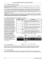
4.1.3.2 Standard Event Status and Standard Event Status Enable Registers
The Standard Event Status Register supplies various conditions of the instrument.
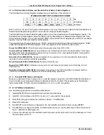
STANDARD EVENT STATUS REGISTER FORMAT
7 6 5 4 3 2 1 0
Bit
128
64 32 16 8 4 2 1
Weighting
PON
not used
CME EXE DDE QYE
not used
OPC
Bit Name
Bits 2 and 6 are not used. The reports of this register occur only if the bits are enabled in the Standard Event
Status Enable Register along with bit 5 of the Service Request Enable Register.
The Standard Event Status Enable Register enables any of the Standard Event Status Register reports. The
Standard Event Status Enable command (*ESE) sets the Standard Event Status Enable Register bits. Set a
bit to enable its function. To set a bit, send the *ESE command with the bit weighting for each bit to set added
together. See the *ESE command for further details.
The Standard Event Status Enable Query, *ESE?, reads the Standard Event Status Enable Register. *ESR?
reads the Standard Event Status Register. Once this register is read, all bits are reset to zero.
Power On (PON) Bit (7)
. This bit is set when the power cycles from OFF to ON.
Command Error (CME) Bit (5)
. Set upon detection of a command error since the last reading. This means
the instrument could not interpret the command due to a syntax error, unrecognized header, unrecognized
terminators, or unsupported command.
Execution Error (EXE) Bit (4)
. Set upon detection of an execution error. Occurs when the instrument is
instructed to do something outside its capabilities.
Device Dependent Error (DDE) Bit (3)
. Reserved for future use.
Query Error (QYE) Bit (2)
. Indicates a query error. Occurs rarely and involves loss of data due to a full
output queue.
Operation Complete (OPC) Bit (0)
. Generated in response to the *OPC (operation complete) common
command. It indicates MPS completion of all selected pending operations.
4.1.4 Example IEEE Setup and Program
Below is an example of how to setup and run a simple program using the built-in MPS IEEE-488 Interface. It
does not reflect every hardware/software configuration found in the field. This example uses the National
Instruments GPIB - PCII/IIA card and QuickBasic 4.0 or 4.5 on a PC compatible.
4.1.4.1 GPIB Board Installation
Use the following procedure to install the GPIB Board.
1.
Install GPIB-PCII/IIA card using National Instruments instructions.
2.
Install NI - 488.2 software (for DOS). Version 2.1.1 was used for the example.
3.
Verify that config.sys contains the command: device = C:\GPIB.COM
4.
Reboot the computer.
5.
Run IBTEST to test software configuration. Do not install the instrument before running IBTEST.
6.
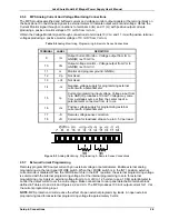
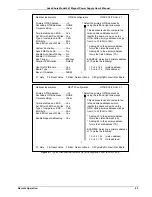
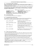
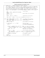
Run IBCONF to configure the GPIB - PCII/IIA board and dev 12. Set the EOS byte to 0AH. See setup in
Fig 4-1. IBCONF modifies gpib.com.
7.
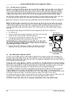
Connect the instrument to the interface board and power up the instrument. Verify the address as 12 and
the terminators as CR LF.

