Lake Shore Model 647 Magnet Power Supply User’s Manual
Remote Operation
4-8
4.2. SERIAL I/O INTERFACE
RS-232C is a standard of the Electronics Industries Association (EIA) and one of the most common interfaces
between a computer and electronic equipment. The Customer supplied computer must have a Serial
Interface port. The MPS Serial Interface complies with the electrical format of the RS-232C Interface
Standard. A Serial Interface between the computer and the MPS permits remote monitoring and control of
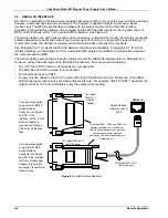
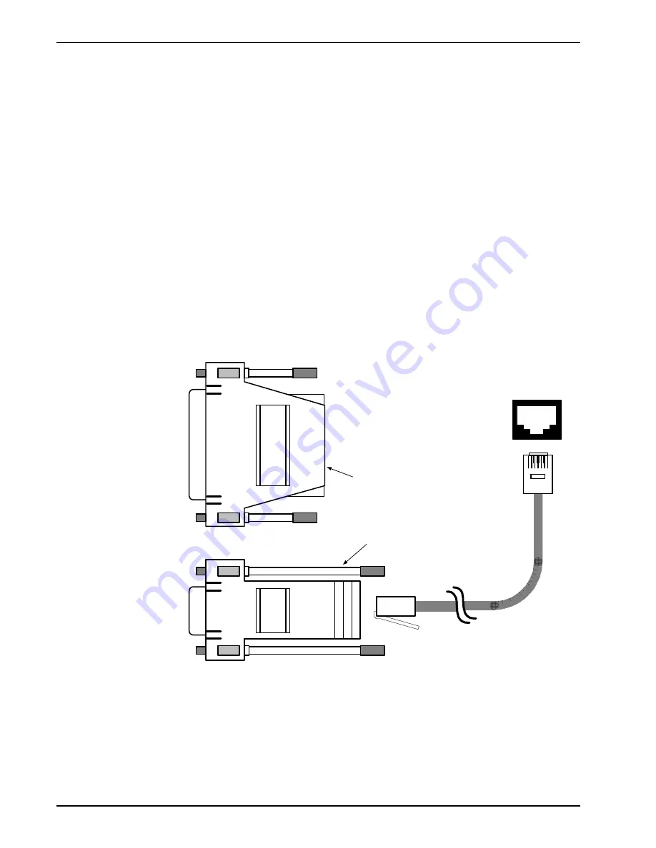
MPS control functions, which in turn controls MPS operation. See Figure 4-2.
The Serial Interface can both transmit and receive information. In transmit (Tx) mode, the instrument converts
parallel information to serial and sends it over a cable up to 50 feet long (or longer with proper shielding). In
receive (Rx) mode, the instrument converts serial information back to parallel for processing.
See Paragraph 4.2.1 for Serial Interface hardware configuration and adapters, Paragraph 4.2.2 for Serial
Interface settings, and Paragraph 4.2.3 for a sample BASIC program to establish communications between
the computer and the MPS.
The Serial Interface shares Device Specific commands with the IEEE-488 interface listed in Paragraph 4.3.
However, without the advantage of the IEEE-488 Architecture, there are several limitations:
• The
∗
OPC and
∗
RST Common Commands are not supported.
• The END Bus Control Command is not supported.
• Terminators are fixed to CRLF.
• A query must be added to the end of a command string if the MPS must return information. (Over IEEE-
488, the last query response is sent when addressed to talk.) For example: “ISET 10;ISET?” would set the
output current to 10 A and immediately query the output current setting.
SERIAL I/O
LSCI Model
2002 RJ-11
to DB-25
Adapter
LSCI Model 2003 RJ-11
to DE-9 Adapter
LSCI Model 2001 RJ-11
Cable Assembly
Serial Interface
Output on rear of
MPS
The Model 2001, 2002, and 2003 are
options available from Lake Shore.
Use whichever adapter that matches
your computer serial interface
connector. Pin outs are described in
Paragraph 6.5.
To customer-supplied
computer with DB-25
Serial Interface
Connector configured
as DCE. If the
interface is DTE, a Null
Modem Adapter is
required to exchange
Transmit and Receive
lines.
To customer-supplied
computer with DE-9
Serial Interface
Connector configured
as DTE. If the interface
is DCE, a Null Modem
Adapter is required to
exchange Transmit and
Receive lines.
1
Figure 4-2
Serial Interface Adapters


