


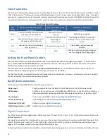


8
Master Interlock Input
The Interlock inpu
t
is the center terminal of a BNC connector located on the back panel of the HVS448. The interlock signal is
TTL-compatible (0–5 V) and weakly pulled to 5 V via an ~20 kΩ internal resistor. When the interlock signal is in its high state (>0.8
V), the high voltage connectors are disconnected from the power supply by relays, and the internal high voltage supply is turned
off. Because of the internal pull-up, a high state can be maintained by leaving the signal open
.
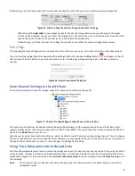
High voltage is enabled by maintaining a TTL low signal (<0.2 V) to the interlock. This can be accomplished by
connecting the
supplied 50-Ω terminator (
Figure 2
) to the interlock connection
,
connecting to an interlock switch to ground, or connecting to a
digital interlock signal that is active low.
To test if the interlock is satisfied (low): on the front panel click the
Enable
then
All
buttons. If the interlock is satisfied this will
enable the high voltage and turn on a green light over the
All
button. If the light is red, the interlock is not satisfied.
Figure 2. 50-Ω
BNC Terminator for Interlock
Disable/Enable High Voltage
Disabling high voltage is a quick way to place the system in a “safe” state. The high voltage connectors on the back panel will
float to the driving voltage when disabled, regardless of the sequence or the states of other channels. High voltage can be
enabled or disabled from the software or using front panel controls. This setting is nonvolatile and is remembered on power-up
.
Disable High Voltage:
•
From the front panel, push
Disable, t
hen
All;
•
or, from the software click the
Disable High Voltage
toolbar button or , choose
Actions>Disable High Voltage
.
When the high voltage is disabled the LED over the ALL button will turn off, or will glow red if the Interlock is not satisfied.
Enable High Voltage:
•
From the front panel, push
Enable, t
hen
All;
•
or, from the software, click the
Enable High Voltage
toolbar button or choose
Actions>Enable High Voltage
.
When the high voltage is enabled the LED over the ALL button will glow green if the interlock is satisfied or red if the Interlock is
not satisfied.
High Voltage Connections
Each channel of the HVS448 includes a single high voltage connector. Each channel can function as a voltage/current source or
monitor, so this connector acts as either an input or output, depending on the function of the channel at any time.
The total system output (all channels considered) will not exceed the maximum unit current (see
Table 1
). The system will
automatically shut down the high voltage supplies if this current is exceeded. Each channel’s maximum and minimum voltage
and current can be limited in software to protect external devices and equipment (see
Channel Output Limits
). Under no
condition will the voltage or current at the channel connection exceed these software limits.
WARNING:
DO NOT connect or disconnect cables from an enabled high voltage channel. Doing so could result in
personal injury and/or damage to the HVS448 or external equipment. You must disable the high
voltage connectors or turn off the HVS448 before plugging or removing equipment. Use the Disable
HV button
on the toolbar or select Actions> Disable High Voltage from the dropdown menu tab.
WARNING:
Do NOT connect a high voltage channel to a digital input or output. While the digital inputs and
outputs are protected to 115 VAC, connecting these different voltage levels could damage the HVS448
and/or any connected equipment.


