


24
Trigger Logic in a Sequence
Four BNC inputs, in1 through in4, accept external trigger signals. These inputs are normally high, which represents a logical FALSE
trigger value. Tying an input’s voltage low sets the trigger value to a logical 1, or TRUE.
Each channel has a trigger output. The outputs of channels A, B, C, and D are connected to the back-panel BNC connectors
labeled outA, outB, outC, and outD, respectively, allowing these channels to trigger external apparatus.
Each channel also has a trigger input, which you can program to be any logical comparison of signals from in1 through in4 and/or
outA through outH. The default trigger logic for a channel input is:
trigger = FALSE;
meaning, “the channel’s trigger will never be set.”
Trigger logic can be more complex, as in:
trigger = outB and not in1;
which means, “this channel’s trigger will be set if Channel B sets its trigger output WHILE input in1 is FALSE.”
Trigger logic can be different for each sequence step:
StepA: Run Initialize;
trigger = FALSE; //the trigger is never set during StepA
StepB: Continue;
trigger = in1;
//the channel can be triggered off the external input
in1, during StepB
Note
:
As in the example above, comments can be added to a sequence by placing “//” before the comment text.
If you define trigger logic for a channel in Step A it does not automatically carry over to Steps B and C; those steps will retain the
default trigger logic until you change it.
Triggers isolate communication channels in a way that is not possible with flags, reducing the potential for software bugs. For
example, the earlier example of coordinating channels to make complementary square waves may be better implemented using
triggers rather than flags. Then another channel
cannot
accidentally change the coordination of the channels by setting the flag.
Fixed Trigger Logic for the Master Sequence
The trigger condition for the master sequence is set to
trigger= outGND
which is always a logical TRUE. Unlike the channels, the logic for the master cannot be changed. The Master can only be triggered
via a
Force Trigger
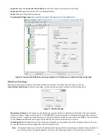
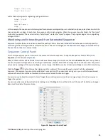
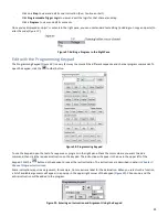
. To do so, in the Sequence Control Panel (
Figure 18
) click the Master
Force Trigger
button. Alternately,
on the HVS front panel press
Trigger
, then press
ALL
.
Trigger Set, Clear and Read in a Program
The trigger output of a channel can be set or cleared using the “Output Set” and “Output Clear” instructions.
The trigger input state can be tested using the commands “InputSet?” and “InputClear?”
If the condition is true, the next instruction will be executed; if it is false, the next instruction will be skipped.
Sequence and Program Flow
A one-instruction program executes in response to an internally generated step switch instruction (see
SwitchTo
), a “Run” Step
command, or simply a “Run” command. This program can be only one of two instructions: “Continue” or “Run X”, where X is the
name of a channel program. At the same time, the input trigger logic switches to the prescribed logic setting.
An example channel sequence could be:
StepA: Run Initialize;
trigger = FALSE; // the trigger for this channel is always FALSE during StepA
StepB: Run Inject;
trigger = in1;
// the trigger responds to input in2 during StepB


