


20
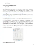
Two other fault conditions are monitored. You don’t have the ability to change these behaviors:
Fault
Meaning
If box is checked
If box is not checked
Error Message
Temperature
limit exceeded
The sensor in the HVS
indicates excessive heat
Channel becomes
an input
Channel becomes an input
(cannot ignore this fault)
“The supply exceeded
its safe operating
temperature.”
Interlock open
(low)
The interlock input is set
to High.
Channel becomes
an input
Channel becomes an input
(cannot ignore this fault)
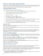
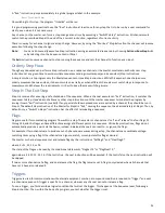
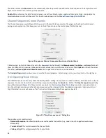
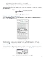
Manual Power Supply Control Panel
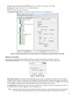
We have just seen that the settings for each channel can be set manually using the individual channel control panels. An
overview of all channels can also be viewed. Click on
High Voltage Power Supply/Monitor
in the left pane to open the
Manual
High-Voltage Power Supply
Controls
dialog box.
Figure 14. Manual High Voltage Power Supply Control Panel
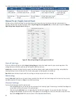
Overall Settings
At the top of the control panel, set the
Output Voltage Range
to a value that makes sense for your current experiment. The
voltage and current sliders for each channel will adjust to reflect your choice.
Update All
synchronizes the data from all channels, reads the calibration data, updates all channel settings, and updates the
monitored values once for all channels. This function also appears on the Sequencer Control Panel.
Reset All
makes all channels inputs, clears all error flags, and stops a sequence if one is running.
Monitoring
Select the
Monitor?
check box next to each channel to display that channel’s real time Voltage and Current values. You can also
click
All
to monitor all channels, or
None
to turn off all monitoring.
Channel Settings
You have the following controls for each channel:
-
Click the
Input
button to use the channel as a voltmeter for an incoming signal. If monitoring is selected, the voltage and
current boxes will show the values of the external signal.
-
Click and drag the
left slider
to set a target voltage for the channel to regulate. As you move the slider, the target
voltage will be displayed. You can also enter the target value in the Voltage box. You will not be able to move the slider
beyond the
Voltage Limits
for the channel (as set in the
Channel Control Panels
).


