

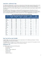


16
CHAPTER 4.
SEQUENCE SOFTWARE OVERVIEW
Sequence™ software lets you set the HVS448’s high voltage functions. The sourcing and sensing functions can be set manually via
control panels for each channel. The Sequence programming environment lets you create sequences that automatically control
and change the voltage settings. Sequence wizards help simplify the process of defining sequences.
Field Upgradeable Firmware
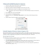
The HVS448 firmware is field upgradeable. To upgrade the firmware:
1.
Download the latest version of Sequence from
www.labsmith.com
or from a link sent to you by LabSmith.
2.
Turn off the HVS448 and disconnect everything from the high voltage outputs.
3.
Connect the HVS448 to your computer and turn on the unit.
4.
Run the Sequence software.
5.
Enter
Online
mode by clicking the
toolbar button.
6.
Choose
Actions>Update Firmware>Update All
. Click
OK
to continue.
7.
The firmware update process takes several minutes. Do not disconnect the power or the serial cable during the update.
8.
When all the tasks are done, the system is automatically recalibrated to complete the system upgrade.
9.
To verify the firmware version, go to
Action>Get Versions
. The firmware version number will be displayed in the status
bar. The unit must be Online for the firmware version to be displayed.
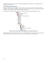
Sequence Files
A Sequence file maintains the last manual settings for each channel, as well as all of the programming for a single automated
sequence. Sequence files have a .seq extension.
To open a Sequence file, choose
File>Open
, then locate the file on your hard drive. You can also choose from recently opened
files at the bottom of the
File
menu.
When you turn on the HVS448, all of the high voltage channels act as “Inputs;” that is, they float to the driving voltage (if no
external source is supplied, then they will indicate near 0 V). When you open a Sequence file, the channels
remain
inputs. Click
the
Update All
button at the bottom of Sequence’s right pane to set all of the channels to the last selected settings.
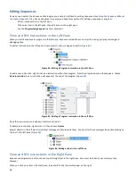
Online and Offline Operation
Sequence functions in either
Online
or
Offline
modes. When
Online
, Sequence communicates with the HVS448, allowing control
and monitoring from a PC. When
Offline
, Sequence does not communicate with the HVS448, but it does record your settings and
programming which can later be stored in the HVS448.
By default, on startup, Sequence is
Offline
. Click the
toolbar button to switch between
Offline
and
Online
modes. The
mode is reported in the status bar at the bottom of Sequence’s main window. When Sequence is instructed to go
Online
, it
automatically programs the HVS448 with the manual power supply settings.
You can also put the HVS448
Online
by going to
View>Option>Communications
. When the correct serial port is selected the
HVS448 will automatically toggle to
Online
mode.
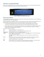
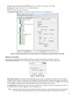
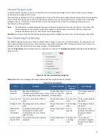
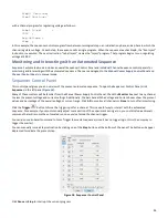
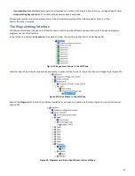
Sequence Software Environment
Figure 10
shows the Sequence main window.
This standard Windows interface includes menus and toolbars to access virtually all functions. These options will be discussed
throughout the body of the text. A complete list of menu and toolbar options is also available in
Appendix 1.
The left pane lets you navigate through the manual controls for each high voltage channel, as well as through the various parts of
an automated sequence. You can collapse or expand levels to access the settings you need while hiding extraneous functions. To
expand a level, click the “+” button to the left of that item; to collapse a level, click the “–” button.
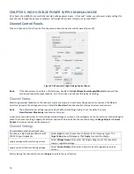
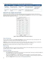
Click on an item in the left pane to view related settings in the right pane:
-
High Voltage Power Supply/Monitor
opens the
Power Supply Control Panel
, an overview of the channels’ manual settings
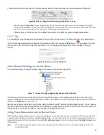
-
Channel A–H
opens the manual settings for a particular channel


