60
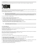
26) MEANING OF BUZZER AUDIBLE SIGNALS
The electronic control unit of the automation is equipped with a buzzer emitting audible signals, whose meaning varies according to the
number of beeps and the sound duration.
AUDIBLE SIGNAL (BEEP)
MEANING
5 short fast BEEPS
Automation not set‑up when powered.
4 short BEEPS
Warning related to the start of the slow opening manoeuvre
during the initial phase of the set-up cycle.
Extended sound (3 seconds)
Signals the end of the initial set-up.
Extended and intermittent sound
(during motion)
The power limit that the automation can supply to the
motor is exceeded while the leaf is moving. This signal is
active if function F49 = OFF.
To disable this warning set F49 to ON.
1 BEEP
After powering the automation (already started up before).
1 extended BEEP (2 seconds)
Motor / encoder disconnected or not working.
1 BEEP (before the opening)
Safety sensor test during opening failed and subsequent
opening at slow speed.
1 BEEP (before the opening)
Battery failure or low battery charge warning.
2 BEEPS (before the closing)
Safety sensor test during closing failed and subsequent
closing at slow speed.
1 extended BEEP (2 seconds)
Internal system failure.
27) MAINTENANCE PROGRAM
To ensure that the automatic door keeps running safely over time, it is recommended to carry out the maintenance operations once every
6 months.
The installer can set the number of opening/closing cycles after which the message "PROGRAMMED MAINTENANCE" will appear on
the display of the selector ET‑DSEL or T‑NFC (potentiometer P48).
Warning!
Before starting the operations on the automation, cut off the main supply line.
•
Check that all the setscrews are correctly tightened.
•
Clean and lubricate all the sliding and mobile components.
•
Check all the connections of the wirings.
•
Check that the setscrew of the arm is correctly tightened.
•
Check that the leaf is steady and that the movement is smooth and without friction from ”door open” position up to “door closed”
position.
•
Check the conditions of the hinges and lubricate them.
•
Check that speed, times, and safety functions are correctly selected.
•
Check for the correct operation of the activation sensors and the safety sensors.
•
Verify, in event of a power outage, that the door closes by means of the spring at a controlled speed without becoming dangerous.
Once maintenance is completed, reset the partial cycle counter and the event memory (see paragraph 19 "MAINTENANCE").
Warning!
Any potentially damaged or worn component must be replaced.
Make use of original spare parts only; for this purpose check LABEL Parts list.
Содержание NEXT 120s
Страница 2: ......
Страница 11: ...11 X 36mm X 6 mm 6 2 SLIDING PUSH ARM NEXT120 BDS STANDARD TAPERED PIN NEXT EXT EXTENSION TAPERED PIN ...
Страница 12: ...12 x X 36mm X 6 mm 6 3 ARTICULATED PUSH ARM NEXT120 BAS STANDARD TAPERED PIN NEXT EXT EXTENSION TAPERED PIN ...
Страница 13: ...13 X 91mm X mm 6 4 ELBOW SLIDING PULL ARM NEXT120 B150 STANDARD TAPERED PIN NEXT EXT EXTENSION TAPERED PIN ...
Страница 14: ...14 X 91mm X mm 6 5 ELBOW SLIDING PULL ARM NEXT120 B250 STANDARD TAPERED PIN NEXT EXT EXTENSION TAPERED PIN ...
Страница 62: ...62 ...
Страница 63: ...63 ...


