25
10.4) FUNCTIONAL TESTING
Select the automatic operation of the door using the program selector.
Bring the manual program selector to position I, if you use it.
Refer to the “Program selectors” paragraph describing the types of selector provided for to select the automatic door operating mode.
To start an opening movement, press briefly the button PS1 (Start) on the control unit NEXT-L120S or engage the door opening devices.
Ensure that the door opening and closing cycle is properly performed and that thrust organs and safety sensors operate; to adjust the
sensor detection range, refer to the instructions provided with the sensor.
The opening safety sensor detects the presence of any side wall at the end of the opening run thanks to the automatic learning function
during the initial set-up.
Should you need to change the optical adjustment of the safety sensor after performing the initial setup of the automation, you can
change the opening safety sensor inhibition distance by editing the potentiometer P03 (see paragraph "Potentiometer adjustment").
During door movement, intermittent signals emitted by the buzzer may be heard. They indicate that the limit power delivered by the
automation has been reached, especially if leaf dimensions and weight are close to the limits allowed.
A short noise signal by the buzzer during start in opening is to be considered as normal, as the pick-up phase requires maximum force.
Adjust the thrust power using the potentiometer P32 of the ET-DSEL selector (see paragraph “Potentiometer adjustment”).
To disable the buzzer noise signal when the power limit is reached, set the F49 function to ON (see “Functions setup”).
The buzzer noise for almost the entire run means that the leaf exceeds the limits allowed, or that the installation
dimensions indicated in the assembly technical drawings were not respected, or that frictions exist on the door; in this
case, the movements of the automatic door are not smooth and the opening/closing cycle may not be completed.
Safety on impact: make sure that the door stops and that the direction of movement is reversed if the motion of the door is prevented.
To set up the available functions, refer to the paragraph “Functions setup”.
To adjust the variable parameters, refer to section “Potentiometer adjustment”.
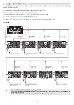
REPEATING THE INITIAL SETUP
Setup operation must be repeated if one of the following conditions changes:
leaf weight, leaf run, in case of arm removal (see paragraph 5.5).
In this case, select the PARTIAL option from “SETUP MODE” to perform only the leaf run learning without changing the current settings.
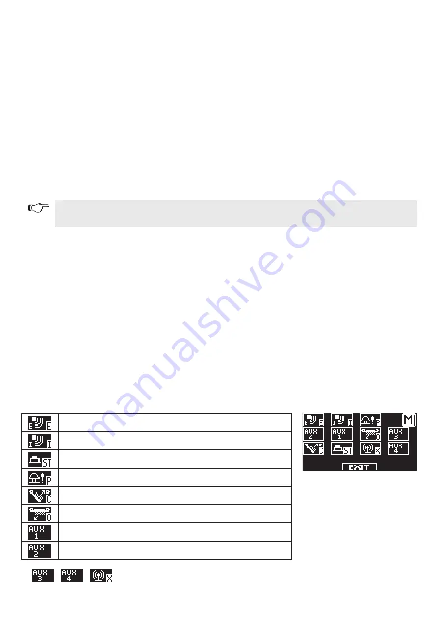
10.5) INPUT DIAGNOSTICS
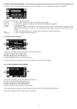
The selector ET-DSEL allows checking the inputs status to ensure proper operation of all devices connected with the automation
NEXT 120S.
To enter “Input Diagnostics” while the automatic door operating program is shown on the display, hold the button F2 pressed for about 3
seconds.
The letter M is displayed on the top right.
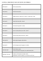
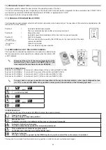
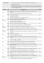
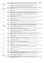
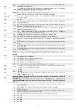
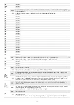
The display shows the symbols of all automation inputs.
If an input is activated, the corresponding symbol lights up with an arrow nearby.
External radar
Internal radar
PS1 (start button) or RX1 radio control
OPEN
Closing safety sensor
Opening safety sensor
AUX 1 (activates if the manual program selector is in position I)
AUX 2 (activates if the manual program selector is in position II)
,
,
=
NOT USED
Содержание NEXT 120s
Страница 2: ......
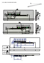
Страница 11: ...11 X 36mm X 6 mm 6 2 SLIDING PUSH ARM NEXT120 BDS STANDARD TAPERED PIN NEXT EXT EXTENSION TAPERED PIN ...
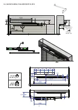
Страница 12: ...12 x X 36mm X 6 mm 6 3 ARTICULATED PUSH ARM NEXT120 BAS STANDARD TAPERED PIN NEXT EXT EXTENSION TAPERED PIN ...
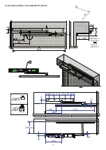
Страница 13: ...13 X 91mm X mm 6 4 ELBOW SLIDING PULL ARM NEXT120 B150 STANDARD TAPERED PIN NEXT EXT EXTENSION TAPERED PIN ...
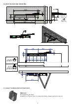
Страница 14: ...14 X 91mm X mm 6 5 ELBOW SLIDING PULL ARM NEXT120 B250 STANDARD TAPERED PIN NEXT EXT EXTENSION TAPERED PIN ...
Страница 62: ...62 ...
Страница 63: ...63 ...

