


2/6/2006
3
Addendum – Ballast Relocation
WARNING! It is imperative that the pins of the bulbs and the shelf power cords be
completely seated in their respective lamp holder or receptacle (see pictures below). If they are
not completely seated, an electrical arc could occur which will cause the lamp holders to melt and
become an electrical hazard. Care must be taken during cleaning, product stocking and re-
lamping processes to insure that the bulbs and shelf cords are not dislodged.
Note:
The fluorescent bulb is capable of lighting even if the bulb and shelf power cord are not
completely seated.
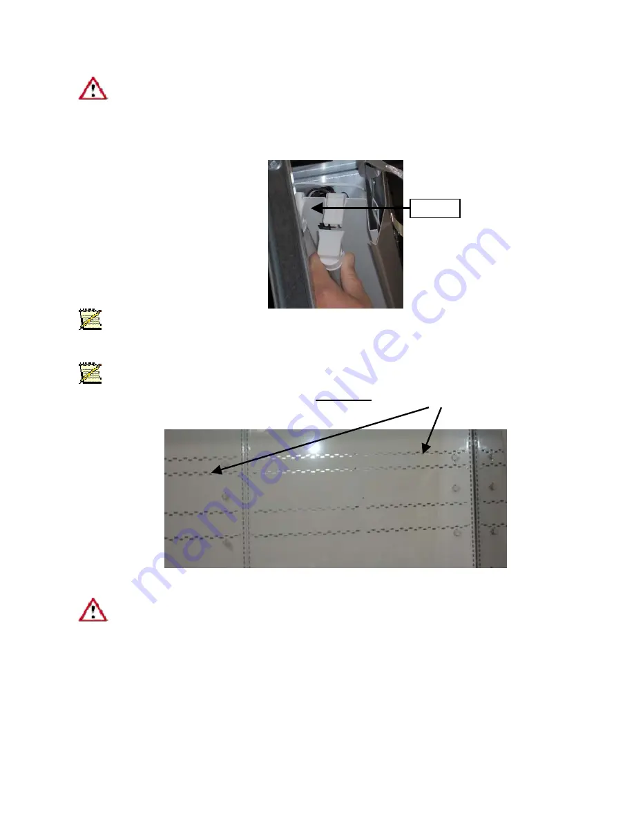
Note:
The shelf light harness has power interruption circuit and ALL shelves must be plugged in
correctly before any shelf lights will work. The
shelf plugs
are now located on the right side of each
back panel. (See picture below).
WARNING! Always disconnect the electrical power at the main disconnect when servicing
or replacing any electrical component. This includes, but is not limited to, such items as fans,
heaters, thermostats and light bulbs. Failure to disconnect the electrical power may result in
personal injury or death.
Bulbs
3
Содержание 6RLG3
Страница 3: ...2 6 2006 2 Addendum Ballast Relocation 2 ...
Страница 5: ...2 6 2006 4 Addendum Ballast Relocation Wiring Diagram Both Canopy and Raceway 4 ...
Страница 6: ...2 6 2006 5 Addendum Ballast Relocation Wiring Diagram for Canopy Light 5 ...
Страница 9: ...Plan Views and Cross Sections D6L D6 D6H 8 ...
Страница 10: ...D6RL D6R 9 ...
Страница 11: ...QD6 10 ...
Страница 12: ...HQD6 8 11 16 44 1 16 39 11 16 4 23 5 8 6 80 9 16 43 1 8 32 1 16 59 13 16 50 1 16 22 15 5 8 L OAD LIMIT 11 ...
Страница 34: ...D6 Electrical Model Table QD6 1 3 04 Through D6H 1 3 6 UNIT INSTALLATION 33 ...
Страница 35: ...D6 Electrical Model Table D6H 1 3 6 Through D6R 1 3 4 UNIT INSTALLATION 34 ...
Страница 36: ...D6 Electrical Model Table D6R 1 3 4 Through D6RL G 1 6 UNIT INSTALLATION 35 ...
Страница 39: ...Wiring Diagram UNIT INSTALLATION 38 ...
Страница 40: ...Wiring Diagram Canopy One 1 and Two 2 Light Rows UNIT INSTALLATION 39 ...
Страница 41: ...Wiring Diagram Canopy Two 2 and Three 3 Light Rows UNIT INSTALLATION 40 ...
Страница 42: ...Wiring Diagram Canopy Two 2 Light Rows and Nose Light UNIT INSTALLATION 41 ...
Страница 43: ...Wiring Diagram Off Cycle Defrost UNIT INSTALLATION 42 ...