


Case Trim Selection (3000 Series Only)
Case Trim Selection (3000 Series Only)
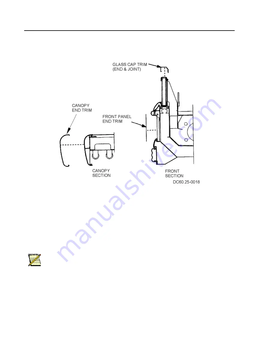
FOR CASES IN A LINEUP:
o Canopy End Trim - two per lineup
o Glass Cap End Trim – two per lineup
o Glass Cap Joint Trim – one per joint
o Front Panel End Trim – two per lineup
FOR SINGLE CASE W/ TWO ENDS:
o No end trim is required.
Note:
If a mutual end is used in a lineup, the proper additional pieces of trim should be
used.
Waste Outlet (Drip Pipe) Description and Location
These cases are equipped with 1 ½" M-NPT waste outlet connection that terminates in the center
of the refrigerator below the insulated bottom. The water seal trap is shipped loose for field
installation.
UNIT INSTALLATION
26
Содержание 6RLG3
Страница 3: ...2 6 2006 2 Addendum Ballast Relocation 2 ...
Страница 5: ...2 6 2006 4 Addendum Ballast Relocation Wiring Diagram Both Canopy and Raceway 4 ...
Страница 6: ...2 6 2006 5 Addendum Ballast Relocation Wiring Diagram for Canopy Light 5 ...
Страница 9: ...Plan Views and Cross Sections D6L D6 D6H 8 ...
Страница 10: ...D6RL D6R 9 ...
Страница 11: ...QD6 10 ...
Страница 12: ...HQD6 8 11 16 44 1 16 39 11 16 4 23 5 8 6 80 9 16 43 1 8 32 1 16 59 13 16 50 1 16 22 15 5 8 L OAD LIMIT 11 ...
Страница 34: ...D6 Electrical Model Table QD6 1 3 04 Through D6H 1 3 6 UNIT INSTALLATION 33 ...
Страница 35: ...D6 Electrical Model Table D6H 1 3 6 Through D6R 1 3 4 UNIT INSTALLATION 34 ...
Страница 36: ...D6 Electrical Model Table D6R 1 3 4 Through D6RL G 1 6 UNIT INSTALLATION 35 ...
Страница 39: ...Wiring Diagram UNIT INSTALLATION 38 ...
Страница 40: ...Wiring Diagram Canopy One 1 and Two 2 Light Rows UNIT INSTALLATION 39 ...
Страница 41: ...Wiring Diagram Canopy Two 2 and Three 3 Light Rows UNIT INSTALLATION 40 ...
Страница 42: ...Wiring Diagram Canopy Two 2 Light Rows and Nose Light UNIT INSTALLATION 41 ...
Страница 43: ...Wiring Diagram Off Cycle Defrost UNIT INSTALLATION 42 ...