background image

SERVICE

MANUAL

Published in November 2009

843LL113

3LLSM063

Rev. 3

DP-750/DP-750(B)

DP-760/DP-760(B)

Содержание DP-750

Страница 1: ...SERVICE MANUAL Published in November 2009 843LL113 3LLSM063 Rev 3 DP 750 DP 750 B DP 760 DP 760 B ...

Страница 2: ...icials for details in your area for proper disposal ATTENTION IL Y A UN RISQUE D EXPLOSION SI LA BATTERIE EST REMPLACEE PAR UN MODELE DE TYPE INCORRECT METTRE AU REBUT LES BATTERIES UTILISEES SELON LES INSTRUC TIONS DONNEES Il peut être illégal de jeter les batteries dans des eaux d égout municipales Vérifiez avec les fonc tionnaires municipaux de votre région pour les détails concernant des déche...

Страница 3: ...rks 1 November 26 2008 1 3 2 1 3 3 1 3 5 1 3 8 1 3 13 1 3 17 to 1 3 19 2 4 1 2 August 6 2009 CONTENTS 1 1 1 1 2 1 1 3 1 1 3 23 to 1 3 46 1 4 2 to 1 4 5 1 5 10 1 6 1 3 November 26 2009 1 1 1 1 3 3 1 3 4 1 3 8 1 3 10 to 1 3 12 1 4 2 1 4 3 2 4 1 to 2 4 3 ...

Страница 4: ...This page is intentionally left blank ...

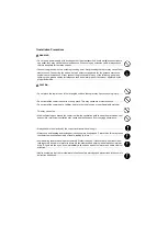
Страница 5: ...rsonnel to ensure the safety of their customers their machines as well as themselves during maintenance activities Service personnel are advised to read this booklet carefully to familiarize themselves with the warnings and precautions described here before engaging in maintenance activities ...

Страница 6: ... this symbol CAUTION Bodily injury or damage to property may result from insufficient attention to or incorrect compliance with warning messages using this symbol Symbols The triangle symbol indicates a warning including danger and caution The specific point of attention is shown inside the symbol General warning Warning of risk of electric shock Warning of high temperature indicates a prohibited ...

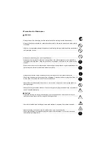
Страница 7: ... or dusty place This may cause fire or electric shock Do not install the copier near a radiator heater other heat source or near flammable material This may cause fire Allow sufficient space around the copier to allow the ventilation grills to keep the machine as cool as possible Insufficient ventilation may cause heat buildup and poor copying performance Always handle the machine by the correct l...

Страница 8: ... carefully Always check that the copier is correctly connected to an outlet with a ground connection Check that the power cable covering is free of damage Check that the power plug is dust free If it is dirty clean it to remove the risk of fire or electric shock Never attempt to disassemble the optical unit in machines using lasers Leaking laser light may damage eyesight Handle the charger section...

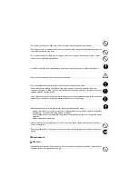
Страница 9: ...r trapped wire and missing screws Check that all the caution labels that should be present on the machine according to the instruction handbook are clean and not peeling Replace with new ones if necessary Handle greases and solvents with care by following the instructions below Use only a small amount of solvent at a time being careful not to spill Wipe spills off completely Ventilate the room wel...

Страница 10: ...This page is intentionally left blank ...

Страница 11: ... Self diagnostic function 1 4 8 2 Self diagnostic codes 1 4 8 1 4 3 Electric problems 1 4 10 1 4 4 Mechanical problems 1 4 11 1 5 Assembly and Disassembly 1 5 1 Precautions for assembly and disassembly 1 5 1 1 Precautions 1 5 1 1 5 2 Assembly and disassembly 1 5 2 1 Detaching and refitting the DP original feed belt and DP forwarding pulley 1 5 2 2 Detaching and refitting the DP separation pulley 1...

Страница 12: ...f the PWBs 2 3 1 DP driver PWB 2 3 1 2 3 2 SHD PWB dual scan DP only 2 3 7 2 4 Appendixes List of maintenance parts 2 4 1 Periodic maintenance procedures 2 4 2 Wiring diagram reversed DP 2 4 5 Wiring diagram dual scan DP 2 4 6 ...

Страница 13: ...45 to 160 g m2 Loading capacity 100 sheets 50 to 80 g m2 maximum Mixed original sizes auto selection 30 sheets 50 to 80 g m2 maximum Power source Electrically connected to the machine Dimensions 577 W x 534 D x 180 H mm 22 11 16 W x 21 D x 7 1 16 H Weight Reversed DP 14 kg or less 30 8 lbs or less Dual scan DP 14 kg or less 30 8 lbs or less NOTE These specifications are subject to change without n...

Страница 14: ...LL 3LK 1 1 2 1 1 2 Parts names Figure 1 1 1 5 7 1 4 3 6 2 2 1 Original tray 2 Original width guides 3 Original eject table 4 Original stopper 5 DP top cover 6 Switchback tray 7 Cleaning cloth compartment ...

Страница 15: ...3LL 3LK 1 1 3 1 1 3 Machine cross section Figure 1 1 2 Machine cross section 3 1 2 Original path 1 Original feed section 2 Original conveying section 3 Original switchback eject sections ...

Страница 16: ...3LL 3LK 1 1 4 This page is intentionally left blank ...

Страница 17: ...gh humidity or low temperature and low humidity an abrupt change in the environmental temperature and cool or hot direct air Avoid places subject to dust and vibrations Choose a surface capable of supporting the weight of the machine Place the machine on a level surface maximum allowance inclination 1 Avoid air borne substances that may adversely affect the machine or degrade the photoconductor su...

Страница 18: ...d 6 Front pad 7 Accessory case 8 Original mat holder 9 Plastic sheet 10 Cleaning cloth 11 Air padded bag 12 Fixing fittings 13 Angle control fitting 14 Plastic bag 15 M4 x 14 TP screws 16 Pin 17 M2 6 x 8 TP screws 18 Air padded bag 19 DP relay PWB 20 Plastic bag 21 Original mat 22 Gasket 23 Plastic bag 24 Installation guide 25 Operation procedure label 26 Original face up label Dual scan DP only ...

Страница 19: ...the tapes and pad Procedure 1 Remove five tapes Figure 1 2 2 2 Open the DP top cover and original width guides 3 Remove the pad Figure 1 2 3 Tape Tape Tape Tape Tape Pad Original width guide Original width guide DP top cover ...

Страница 20: ...3LL 3LK 1 2 4 This page is intentionally left blank ...

Страница 21: ...using the numeric keys Enter 001 using the cursor up down keys or numeric keys and press the start key Enter the maintenance item number using the cursor up down keys or numeric keys The selected maintenance item is run Press the stop key Press the start key Start End Maintenance mode is entered The maintenance item is selected Maintenance mode is exited Repeat the same maintenance item Run anothe...

Страница 22: ...45 U091 Setting the white line correction Operation panel and support equipment U203 Operating the DP separately U243 Checking the operation of the DP motors U244 Checking the DP switches Mode setting U326 Setting the black line cleaning indication ON 1 8 Image processing U404 Adjusting margins for scanning an original from the DP 3 0 2 5 3 0 4 0 3 0 2 5 3 0 4 0 U411 Adjusting the scanner automati...

Страница 23: ...ion Framework Framework COLOR TABLE1 Color table1 COLOR TABLE2 Color table2 MOTOR CPU Motor CPU MOTOR CPU BOOT Motor CPU booting H VLT CPU High voltage CPU H VLT CPU BOOT High voltage CPU booting SLEEP CPU Sleep CPU SLEEP CPU BOOT Sleep CPU booting DP Optional DP ROM 500x2PF Optional paper feeder ROM 3000PF Optional 3000 sheet paper feeder ROM 1000DF Optional document finisher ROM 3000DF MAIN Opti...

Страница 24: ...e left when the setting value is decreased 4 Press the start key The value is set 5 Select TEST POSITION of the screen for selecting an item 6 Select the scanning position using the or numeric keys 7 Press the start key The value is set 8 Set the original the one which density is known in the DP and press the system menu key The screen for the test copy mode is displayed 9 Press the start key Test...

Страница 25: ...start key The value is set Caution Check the copy image after the adjustment If the image is still incorrect perform the following adjustments in maintenance mode Completion Press the stop key The screen for selecting a maintenance item No is displayed Maintenance item No Description Display Description Setting range Initial setting Change in value per step CONVEY SPEED1 Magnification in the auxil...

Страница 26: ...alue is set Caution If the CCD first side is adjusted check the CCD second side and if adjustment is required carry out the adjustment Check the copy image after the adjustment If the image is still incorrect perform the following adjustments in maintenance mode Maintenance item No Description Display Description Setting range Initial setting Change in value per step ADJUST DATA1 Leading edge regi...

Страница 27: ...decrease the value Figure 1 3 3 5 Press the start key The value is set Caution If the CCD first side is adjusted check the CCD second side and if adjustment is required carry out the adjustment Check the copy image after the adjustment If the image is still incorrect perform the following adjustments in maintenance mode Completion Press the stop key The screen for selecting a maintenance item No i...

Страница 28: ...is adjusted check the CCD second side and if adjustment is required carry out the adjustment Check the copy image after the adjustment If the image is still incorrect perform the following adjustments in maintenance mode Completion Press the stop key The screen for selecting a maintenance item No is displayed Maintenance item No Description Display Description Setting range Initial setting Change ...

Страница 29: ...key 2 Select the item to be set Setting CCD 1 Select the item to be set 2 Change the value using the or numeric keys 3 Press the start key The value is set Method BLACK LINE 1 Select CLEAR 2 Press the start key The setting is cleared Completion Press the stop key The screen for selecting a maintenance item No is displayed Maintenance item No Description Display Description CCD Setting of standard ...

Страница 30: ...ow to view test copies Setting Threshold value setting 1 Select the item to be set 2 Change the value using the or numeric keys Normally the Threshold Com value should not be changed from 112 the initial setting If white lines appear even though the CIS roller and glass are not dirty raise the set value If fine lines in some originals disappear lower the set value Set within the range 50 to 200 If...

Страница 31: ... The operation starts 5 To stop continuous operation press the stop key Completion Press the stop key when the operation stops The screen for selecting a maintenance item No is displayed Maintenance item No Description Display Description Setting range Initial setting CCD ADP NON P Without paper single sided original of CCD continuous operation CCD ADP With paper single sided original of CCD CCD R...

Страница 32: ...everse Dual scan DP only Completion Press the stop key The screen for selecting a maintenance item No is displayed Maintenance item No Description Display Motor and solenoid Operation DP FEED MOT Original feed motor OFM In operation DP CON MOT Original conveying motor OCM In operation DP REV MOT Original switchback motor OSBM In operation DP LIFT MOT DP lift motor DPLM In operation DP REV PRS SOL ...

Страница 33: ...ss the start key The setting is set Setting BLACK LINE COUNT 1 Change the setting value using the or numeric keys When setting is 0 the black line cleaning indication is displayed only if the black line is detected 2 Press the start key The value is set Completion Press the stop key The screen for selecting a maintenance item No is displayed Maintenance item No Description Display Description BLAC...

Страница 34: ...rt key The value is set Completion Press the stop key The screen for selecting a maintenance item No is displayed Maintenance item No Description U403 See the service manual for the machine U402 See the service manual for the machine U404 Display Description Setting range Initial setting Change in value per step A MARGIN Left margin 0 to 10 0 3 0 0 5 mm B MARGIN Leading edge margin 0 to 10 0 2 5 0...

Страница 35: ...e leading edge main scanning and auxiliary scanning of the specified original P N 302AC68243 and enter the values by executing maintenance item U425 2 Set a specified original P N 302AC68243 in the DP Cut the trailing edge of the original Figure 1 3 6 Maintenance item No Description Display Description Original to be used for adjustment P N SCANNER Automatic adjustment in the scanner section 302FZ...

Страница 36: ...stment of INPUT MTF GAMMA and MATRIX can be executed at once When adjusting place the three specified originals and then press the start key Set the original 303JX57020 and then place 303JX57010 and 302AC68243 in order on the top of the orig inal When automatic adjustment has normally completed COMPLETE is displayed If a problem occurs during auto adjustment ERROR XX XX is replaced by an error cod...

Страница 37: ...t detected DP main scanning direction magnification near end ERROR 0a Black band is not detected DP auxiliary scanning direction magnification leading edge ERROR 0b Black band is not detected DP auxiliary scanning direction magnification leading edge ERROR 0c Black band is not detected DP auxiliary scanning direction trailing edge ERROR 0d Black band is not detected DP auxiliary scanning direction...

Страница 38: ...d for adjustment DP Entering the measurement value of the chart P N 302AC68243 used for adjustment CIS Execution is not required Display Description N875 Setting the N875 patch for the original for adjustment N475 Setting the N475 patch for the original for adjustment N125 Setting the N125 patch for the original for adjustment CYAN Setting the cyan patch for the original for adjustment MAGENTA Set...

Страница 39: ...from the edge to the black belt b of the original at D 30 mm from the left edge E 148 5 mm from the left edge and F 267 mm from the left edge respectively 2 Apply the following formula for the values obtained D F 2 E 2 5 Enter the values solved using the keys in SUB LEAD ADJ 6 Press the start key The value is set 7 Measure the length G from the leading edge of the black belt b to the bottom of the...

Страница 40: ... B 4 Enter the measured value using the keys in MAIN SCAN 5 Measure the distance from the black belt of leading edge inside to the black belt of trailing edge inside of the original at C 6 Enter the measured value using the keys in SUB SCAN 7 Press the start key The value is set Figure 1 3 8 Completion Press the stop key The screen for selecting a maintenance item No is displayed Maintenance item ...

Страница 41: ...escription DP Counts of optional DP FINISHER Counts of optional document finisher or 3000 sheet document finisher Display Description ADP No of single sided originals that has passed through the DP RADP No of double sided originals that has passed through the DP CONCURRENT No of dual scan originals that has passed through the DP Display Description CP CNT No of copies that has passed STAPLE Freque...

Страница 42: ...start key The setting is set Completion Press the stop key The screen for selecting a maintenance item No is displayed U990 Checking clearing the time for the exposure lamp to light Description Displays clears or changes the accumulated time for the CIS to light Purpose To check duration of use of the CIS Also to clear the accumulated time for the CIS after replacement Method 1 Press the start key...

Страница 43: ...numeric keys Enter 001 using the cursor up down keys or numeric keys and press the start key Enter the maintenance item number using the cursor up down keys or numeric keys The selected maintenance item is run Press the stop key Press the start key Start End Maintenance mode is entered The maintenance item is selected Maintenance mode is exited Repeat the same maintenance item Run another maintena...

Страница 44: ...45 U091 Setting the white line correction Operation panel and support equipment U203 Operating the DP separately U243 Checking the operation of the DP motors U244 Checking the DP switches Mode setting U326 Setting the black line cleaning indication ON 8 1 Image processing U404 Adjusting margins for scanning an original from the DP 3 0 2 5 3 0 4 0 3 0 2 5 3 0 4 0 1 U411 Adjusting the scanner automa...

Страница 45: ...BROWSER Browser ROM OPTION LANGUAGE Optional language ROM DICTIONARY DBA Database connection Solution Framework Framework DP DP ROM 500x2PF Optional paper feeder ROM 3000PF Optional 3000 sheet paper feeder ROM 1000DF Optional document finisher ROM 3000DF MAIN Optional 3000 sheet document finisher main ROM 3000DF MIDDLE Optional 3000 sheet document finisher Inner tray ROM MAIL BOX Optional mailbox ...

Страница 46: ...ting value is increased the scanning position moves to the right and it moves to the left when the setting value is decreased 4 Press the start key The value is set 5 Select BLACK LINE of the screen for selecting an item 6 Select the scanning position using the or numeric keys 7 Press the start key The value is set 8 Set the original the one which density is known in the DP and press the system me...

Страница 47: ...ase the value For copy example 2 decrease the value Figure 1 3 9 5 Press the start key The value is set Caution Check the copy image after the adjustment If the image is still incorrect perform the following adjustments in maintenance mode Maintenance item No Description Display Description Setting range Initial setting Change in value per step MOTOR ADJ FRONT Magnification in the auxiliary scanni...

Страница 48: ...For copy example 1 increase the value For copy example 2 decrease the value Figure 1 3 10 5 Press the start key The value is set Caution Check the copy image after the adjustment If the image is still incorrect perform the following adjustments in maintenance mode Completion Press the stop key The screen for selecting a maintenance item No is displayed Maintenance item No Description Original Copy...

Страница 49: ...art key The value is set Caution If the CCD first side is adjusted check the CCD second side and if adjustment is required carry out the adjustment Check the copy image after the adjustment If the image is still incorrect perform the following adjustments in maintenance mode Maintenance item No Description Display Description Setting range Initial setting Change in value per step FRONT HEAD Leadin...

Страница 50: ...decrease the value Figure 1 3 12 5 Press the start key The value is set Caution If the CCD first side is adjusted check the CCD second side and if adjustment is required carry out the adjustment Check the copy image after the adjustment If the image is still incorrect perform the following adjustments in maintenance mode Completion Press the stop key The screen for selecting a maintenance item No ...

Страница 51: ...For copy example 2 decrease the value Figure 1 3 13 7 Press the start key The value is set Caution If the CCD first side is adjusted check the CCD second side and if adjustment is required carry out the adjustment Check the copy image after the adjustment If the image is still incorrect perform the following adjustments in maintenance mode Completion Press the stop key The screen for selecting a m...

Страница 52: ... selected item is displayed Setting Standard data when dust is detected 1 Select the item to be set 2 Change the value using the or numeric keys 3 Press the start key The value is set Setting Initialization of original reading position 1 Select CLEAR 2 Press the start key The setting is cleared Completion Press the stop key The screen for selecting a maintenance item No is displayed Maintenance it...

Страница 53: ... Press the stop key The screen for selecting a maintenance item No is displayed Maintenance item No Description Display Description Calculation R Abnormal pixel count result for color R Calculation G Abnormal pixel count result for color G Calculation B Abnormal pixel count result for color B Display Description Setting range Initial setting Threshold R Setting of abnormal pixel detection thresh o...

Страница 54: ...s the stop key when operation stops The screen for selecting a maintenance item No is displayed Maintenance item No Description Display Description Setting range Initial setting CCD ADP NON P Without paper single sided original of CCD continuous operation CCD ADP With paper single sided original of CCD CCD RADP NON P Without paper double sided original of CCD continuous operation CCD RADP With pap...

Страница 55: ... DP only Completion Press the stop key The screen for selecting a maintenance item No is displayed Maintenance item No Description Display Description FD SW Original feed switch OFSW REG SW Original registration switch ORSW TMG SW DP timing switch 1 DPTSW1 EJT SW Original eject switch OESW TRY SW Switchback tray switch SBTSW SET SW Original set switch OSSW SZ SW A Original size length switch OSLSW...

Страница 56: ...the start key The setting is set Setting BLACK LINE COUNT 1 Change the setting value using the or numeric keys When setting is 0 the black line cleaning indication is displayed only if the black line is detected 2 Press the start key The value is set Completion Press the stop key The screen for selecting a maintenance item No is displayed Maintenance item No Description Display Description BLACK L...

Страница 57: ... 1 3 14 7 Press the start key The value is set Completion Press the stop key The screen for selecting a maintenance item No is displayed Maintenance item No Description U403 See the service manual for the machine U402 See the service manual for the machine U404 Display Description Setting range Initial setting Change in value per step A MARGIN Left margin 0 to 10 0 3 0 0 5 mm B MARGIN Leading edge...

Страница 58: ...rmine the details of the problem and either repeat the procedure from the beginning or adjust the remaining items manually by running the corresponding maintenance items Maintenance item No Description Display Description Original to be used for adjustment P N SCANNER Automatic adjustment in the scanner section 302FZ56990 DP FACE UP Automatic adjustment in the DP scanning section first page 302AC6...

Страница 59: ... press the start key 3 Place the specified original for acquiring matrix target data P N 303JX57020 on the platen and press the start key When normally completed Complete is displayed 4 Select the item place all originals face down Maintenance item No Description F R 5 mm 149 1 mm 74 1 mm Display Description INPUT Automatic adjustment of first page using the DP for original size mag nification lea...

Страница 60: ...ace the three specified originals and then press the start key Set the original 303JX57020 and then place 303JX57010 and 302AC68243 in order on the top of the origi nal When automatic adjustment has normally completed COMPLETE is displayed If a problem occurs dur ing auto adjustment ERROR XX XX is replaced by an error code is displayed and operation stops Should this happen determine the details o...

Страница 61: ...n magnification near end ERROR 0a Black band is not detected DP auxiliary scanning direction magnification leading edge ERROR 0b Black band is not detected DP auxiliary scanning direction magnification leading edge ERROR 0c Black band is not detected DP auxiliary scanning direction trailing edge ERROR 0d Black band is not detected DP auxiliary scanning direction trailing edge 2 ERROR 0e DMA time o...

Страница 62: ...d for adjustment DP Entering the measurement value of the chart P N 302AC68243 used for adjustment CIS Execution is not required Display Description N875 Setting the N875 patch for the original for adjustment N475 Setting the N475 patch for the original for adjustment N125 Setting the N125 patch for the original for adjustment CYAN Setting the cyan patch for the original for adjustment MAGENTA Set...

Страница 63: ...from the edge to the black belt b of the original at D 30 mm from the left edge E 148 5 mm from the left edge and F 267 mm from the left edge respectively 2 Apply the following formula for the values obtained D F 2 E 2 5 Enter the values solved using the keys in SUB LEAD ADJ 6 Press the start key The value is set 7 Measure the length G from the leading edge of the black belt b to the bottom of the...

Страница 64: ... B 4 Enter the measured value using the keys in MAIN SCAN 5 Measure the distance from the black belt of leading edge inside to the black belt of trailing edge inside of the original at C 6 Enter the measured value using the keys in SUB SCAN 7 Press the start key The value is set Figure 1 3 17 Completion Press the stop key The screen for selecting a maintenance item No is displayed Maintenance item...

Страница 65: ...Description DP Counts of optional DP FINISHER Counts of optional document finisher or 3000 sheet document finisher Display Description ADP No of single sided originals that has passed through the DP RADP No of double sided originals that has passed through the DP CONCURRENT No of dual scan originals that has passed through the DP Display Description CP CNT No of copies that has passed STAPLE Frequ...

Страница 66: ...e start key The setting is set Completion Press the stop key The screen for selecting a maintenance item No is displayed U990 Checking clearing the time for the exposure lamp to light Description Displays clears or changes the accumulated time for the CIS to light Purpose To check duration of use of the CIS Also to clear the accumulated time for the CIS after replacement Method 1 Press the start k...

Страница 67: ...ops operation and a message is shown on the machine operation panel To remove the jammed original open the DP top cover or switchback unit Paper misfeed detection can be reset by opening and closing the respective covers to turn safety switch off and on 2 Original misfeed detection conditions Figure 1 4 1 ORSW SBTSW OFSW OESW TULSW DPTSW1 DPTSW2 ...

Страница 68: ... not turn on within specified time of the original registration switch ORSW turning on Retry 5 times 1774 ms 1080 ms During dual scanning the DP timing switch 2 DPTSW2 does not turn on within specified time of the original reg istration switch ORSW turning on Retry 5 times 1014 ms 617 ms 74 An original jam in the original feed sec tion The original feed switch OFSW or original registration switch ...

Страница 69: ...itch 1 2 DPTSW1 2 turning on 79 An original jam in the original eject section During single scanning or dual scanning the original eject switch OESW does not turn on within specified time of the DP timing switch 1 DPTSW1 turning on 1705 ms 1038 ms During duplex switchback scanning the original eject switch OESW does not turn on within specified time since switchback ejection starts 841 ms 512 ms D...

Страница 70: ...n Retry 5 times 1014 ms 74 An original jam in the original feed section The original feed switch OFSW or original registration switch ORSW does not turn off within specified time of the DP timing switch 1 DPTSW1 turning on 2084 ms Scanning of previous original is not complete when DP tim ing switch 1 DPTSW1 turns on 75 An original jam in the original conveying sec tion During single scanning the D...

Страница 71: ...iming switch 1 DPTSW1 turning on 1705 ms During duplex switchback scanning the original eject switch OESW does not turn on within specified time since switchback ejection starts 841 ms During single scanning or dual scanning the original eject switch OESW does not turn off within specified time of the DP timing switch 1 DPTSW1 turning off 1705 ms Section Jam code Conditions Specified time ...

Страница 72: ... corre sponding switch on the touch panel is not displayed in reverse Defective motor Run maintenance item U243 and select the following motor on the touch panel to be turned on and off Check the status and remedy if necessary Original feed motor original conveying motor 4 An original jams in DP is indicated dur ing copying jam in the original registra tion section Jam code 73 Defective switch Run...

Страница 73: ...heck the status and remedy if necessary Original switchback motor original feed motor 9 A original jam in the DP is indicated as soon as the main power switch is turned on DP cover open JAM Jam code 78 A piece of paper torn from original is caught around original feed switch original registration switch or DP timing switch 1 2 Check visually and remove it if any Defective switch Run maintenance it...

Страница 74: ...ut is not obtained at CIS Defective DP driver PWB Replace the DP driver PWB and check for correct operation CIS output prob lem Replace the CIS and check for correct oper ation Defective DP inverter PWB Replace the DP inverter PWB and check for correct operation C9000 DP communication problem A communication error is detected Poor contact in the connector termi nals Check the connection of connect...

Страница 75: ...t operation C9060 DP EEPROM error Read and write data does not match Data in the specified area of the backup memory does not match the specified values Defective DP main PWB Replace the DP main PWB and check for correct operation Device damage of EEPROM Contact the Service Administrative Division C9070 Communication problem between DP and SHD A communication error is detected Loose connection of ...

Страница 76: ...Also check for continuity within the con nector cable If none remedy or replace the cable 2 Defective solenoid Run maintenance item U243 and check if the solenoid operates If not replace the solenoid 3 Defective DP driver PWB Run maintenance item U243 and check if the solenoid operates If not replace the DP driver PWB 3 A message indicating cover open is dis played when the DP is closed correctly ...

Страница 77: ...ce see page 1 5 2 5 2 No secondary original feed The registration pulley and the registration roller do not contact each other correctly Check and clean them with isopropyl alcohol if they are dirty 3 Originals jam Originals outside the specifications are used Use only originals conforming to the specifi cations The surfaces of the DP original feed belt DP forwarding pulley or DP separation pulley...

Страница 78: ...3LL 3LK 1 4 12 This page is intentionally left blank ...

Страница 79: ...cause damage to the equipped hard disk When handling PWBs printed wiring boards do not touch parts with bare hands The PWBs are susceptible to static charge Do not touch any PWB containing ICs with bare hands or any object prone to static charge When removing the hook of the connector be sure to release the hook Take care not to get the cables caught To reassemble the parts use the original screws...

Страница 80: ...e below to replace the DP original feed belt and DP forwarding pulley Procedure 1 Open the DP top cover 2 Remove the screw and then remove the original feed shaft guide Figure 1 5 1 3 Remove the stop ring and then remove the original feed unit from the DP Figure 1 5 2 Original feed shaft guide Screw DP top cover Original feed unit Stop ring ...

Страница 81: ...m the shorter shaft side Slide the pulley and the original feed holder at the longer shaft side 7 Pull out the original feed belt shaft A from the original feed belt unit and then remove the original feed collar A Figure 1 5 4 Original feed belt unit Original feed unit Pin Pin Stop ring Stop ring Pulley Pulley Original feed holder Original feed holder Original feed collar A Original feed belt unit...

Страница 82: ... each two pulleys and pins 12 Pull out the forwarding pulley shaft from the original feed unit and then remove the DP forwarding pulley 13 Check or replace the DP original feed belt and DP forwarding pulley and refit all the removed parts Figure 1 5 6 Original feed belt shaft B Original feed belt unit Original feed collar B DP original feed belt DP forwarding pulley Forwarding pulley shaft Origina...

Страница 83: ... upper shift guide 3 Remove two screws and then remove the lower original feed guide Figure 1 5 7 4 Remove the stop ring and then DP separa tion pulley and torque limiter 5 Check or replace the DP separation pulley and refit all the removed parts Figure 1 5 8 Screw Screw Upper shift guide Lower original feed guide DP top cover Stop ring Torque limiter DP separation pulley ...

Страница 84: ... Open the DP top cover 2 Remove two screws and then remove the DP front left cover Figure 1 5 9 3 Remove the two screws from the back side of document processor 4 Release two inserted parts and then remove the DP front cover Figure 1 5 10 Screw Screw DP front left cover DP top cover Screw DP front cover Inserted parts Screw ...

Страница 85: ...5 Remove the screw and pin and then remove the upper conveying guide Figure 1 5 11 6 Pull out the projection and remove the upper shift guide Figure 1 5 12 Screw Pin Upper conveying guide Upper shift guide Projection ...

Страница 86: ...ver Figure 1 5 13 8 Remove the stop ring and bush 9 Slide the registration roller toward the rear side of machine and let escape the front side of roller as shown in the figure Figure 1 5 14 Conveying cover Registration roller Bush Stop ring ...

Страница 87: ...3 Remove three screws and then remove the CIS Figure 1 5 15 14 Remove the screw and then remove the CIS guide from CIS 15 Replace the CIS and Install the CIS to the DP Caution Be sure to refit the ground wire that has been removed in step 12 16 Refit all the removed parts Figure 1 5 16 Connector Screws Screw DP inverter PWB Ground wire Ground screw Connector CIS FFC CIS guide Screw CIS ...

Страница 88: ...rm maintenance mode U091 setting the white line correction see page 1 3 10 33 20 Make a test copy of a gray document If problems such as white lines appear on the test copy repeat the procedure from steps 18 and 19 onwards until the white lines no longer appear 21 Perform maintenance mode U411 Adjusting the scanner automatically see page 1 3 15 38 ...

Страница 89: ...g fit tings Figure 1 5 18 4 Turn adjusting screw at the rear side of the right hinge to adjust the DP position For copy example 1 Turn the adjusting screw counterclockwise and move the DP to the inner side For copy example 2 Turn the adjusting screw clockwise and move the DP to the front side Amount of change per scale Approx 1 mm 5 Make a test copy 6 Repeat the steps above until the gap of the le...

Страница 90: ...th its Velcro upward over the contact glass Align original mat corner that has 90 degrees of angle with the inner left corner of the original instruction panel 10 Close DP and attach original mat onto it with Velcro Figure 1 5 20 Original mat DP Velcro Original mat ...

Страница 91: ...e For simplex copying Within 3 0 mm For duplex copying Within 4 0 mm Figure 1 5 21 3 Open the DP top cover 4 Remove four screws and then remove the DP rear cover Figure 1 5 22 5 Adjust the height of DP Loosen the nut For copy example 1 Loosen the adjusting screw For copy example 2 Tighten the adjusting screw Amount of change per scale Approx 0 5 mm Retighten the nut 6 Refit the DP rear cover Figur...

Страница 92: ...t corner that has 90 degrees of angle with the inner left corner of the original instruction panel 9 Close DP and attach original mat onto it with Velcro Figure 1 5 24 10 Make a test copy again 11 Repeat steps 1 to 9 above until the gap of the trailing edge falls within the reference values Original mat DP Velcro Original mat ...

Страница 93: ... driver PWB is replaced with a new one carry out the following procedure 1 Clean the CIS roller and contact glass CIS 2 Perform maintenance mode U091 setting the white line correction see page 1 3 10 33 3 Make a test copy of a gray document If problems such as white lines appear on the test copy repeat the procedure from steps 1 and 2 onwards until the white lines no longer appear 4 Perform mainte...

Страница 94: ...3LL 3LK 1 6 2 This page is intentionally left blank ...

Страница 95: ...g pulley and DP original feed belt The DP separation pulley prevents multiple sheets from being fed at one time via the torque limiter Figure 2 1 1 Original feed section 1 3 2 4 9 7 5 6 8 11 10 1 Original tray 2 Original size width switch OWSW 3 Original lift guide 4 DP forwarding pulley 5 DP original feed belt 6 Original feed collar A 7 Original feed collar B 8 DP separation pulley 9 Original set...

Страница 96: ...ure 2 1 2 Original feed section block diagram OFSW DPLM OFM DPDPWB YC5 5 6 7 8 YC5 13 14 15 16 YC7 A11 YC7 B8 YC7 B5 YC7 B11 YC8 6 FEED_ A B A B LFTMOT_ A A B B FDSW LF_L_SW LF_U_SW SET SW SZ SW W OSSW OWSW TLLSW TULSW ...

Страница 97: ...rst side is scanned at the slit glass resulting in simultaneous scanning Figure 2 1 3 Original conveying section 3 13 1 4 6 7 8 9 11 10 12 15 14 2 5 1 Original registration switch ORSW 2 Registration roller 3 Registration pulley 4 DP timing switch 2 DPTSW2 5 Upper conveying roller 6 Conveying pulley 7 CIS roller 8 CIS 9 DP timing switch 1 DPTSW1 10 Left conveying roller 11 Conveying pulley 12 Conv...

Страница 98: ...n block diagram ORSW DPTSW2 DPTSW1 OFM OCM DPINPWB SHDPWB DPRPWB DPDPWB YC7 A8 YC7 A5 YC5 5 6 7 8 YC5 9 10 11 12 YC7 B2 YC3 REGSW CIS_SW FEED_ A _ B A B CONVEY_ A _ B A B TMG_SW Serial communication data signal YC2 YC5 2 YC1 Image data INVREM YC1 YC8 CIS ...

Страница 99: ...ly to the switchback tray and conveyed again to the original conveying section by the switchback roller Figure 2 1 5 Original switchback eject sections 3 5 7 4 6 10 1 9 11 12 14 8 13 2 1 Switchback feedshift guide 2 Eject feedshift guide 3 Upper feedshift guide 4 Switchback roller 5 Switchback pulley 6 Switchback tray switch SBTSW 7 Actuator switchback tray switch 8 Switchback tray 9 Feedshift rol...

Страница 100: ...3LK 2 1 6 Figure 2 1 6 Original switchback eject sections block diagram OESW YC6 5 6 YC10 2 YC5 1 2 3 4 YC10 5 YC6 2 3 JNC_SOL_P K EJ SW DUPLEX_ A B A B TRAY SW PRS_SOL_P R SBFSSOL SBPSOL SBTSW OSBM DPDPWB ...

Страница 101: ...ct table 1 2 3 1 1 Slit glass second side scanning 1 The first side of original is scanned at the slit glass machine main body Conveyed to the switchback tray by the switchback feedshift guide Ejected to the original eject table by the switchback feedshift and eject rollers The second side of original is scanned at the slit glass machine main body and the original is conveyed to the switchback tra...

Страница 102: ...3LL 3LK 2 1 8 This page is intentionally left blank ...

Страница 103: ...ntrols electrical components 2 LED PWB LEDPWB Indicates presence of originals or an original jam 3 SHD PWB SHDPWB Controls the image processing 4 DP inverter PWB DPINPWB Controls the light source of built in CIS 5 DP relay PWB DPRPWB Relay of image data Dual scan DP only 1 5 4 3 2 Machine front Machine inside Machine rear ...

Страница 104: ...switch 1 DPTSW1 Detects the original scanning timing 7 DP timing switch 2 DPTSW2 Detects the original scanning timing 8 Switchback tray switch SBTSW Detects the original in switchback tray section 9 Original eject switch OESW Detects an original misfeed in the original eject section 10 Original size length switch OLSW Detects the length of the original 11 Original size width switch OWSW Detects th...

Страница 105: ... section 2 Original conveying motor OCM Drives the original conveying section 3 Original switchback motor OSBM Drives the switchback roller 4 DP lift motor DPLM Operates the original lift guide 5 DP fan motor DPFM Cools the CIS Dual scan DP only 1 2 3 5 4 Machine front Machine inside Machine rear ...

Страница 106: ...itchback feedshift solenoid SBFSSOL Operates the switchback feedshift guide 2 Switchback pressure solenoid SBPSOL Operates the switchback pulley 3 CIS CIS Reads the image of originals Dual scan DP only 1 3 2 Machine front Machine inside Machine rear ...

Страница 107: ...ONVEY_ A B A B DUPLEX_ A B A B LFTMOT_ A B A B 5V1 24V1 R24V R24V 24V Serial communication data SHDPWB 5V 24V Driver U7 EEPROM U2 Driver U8 Driver U9 Driver U10 OFM SBFSSOL SBPSOL LEDPWB DPDPWB DPTSW2 ORSW OFSW DPTSW1 TULSW TLLSW OSSW DPOCSW OESW SBTSW OLSW OWSW CIS_SW REGSW FDSW TMG_SW LF_U_SW LF_D_SW SET SW DP_OPNSW EJ SW TRAY SW SZ DET SZ_SW_W OCM OSBM DPLM DPILSW Serial communication data ...

Страница 108: ... 2 DP driver PWB silk screen diagram YC11 YC2 YC5 YC1 U2 U1 U8 U7 U9 U10 YC12 YC3 YC7 YC10 YC13 YC8 YC6 YC4 YC14 U5 U15 U3 U4 U6 U13 U14 1 1 15 16 1 2 12 16 4 1 7 1 1 2 A2 A1 1 1 5 9 6 1 5 1 1 2 6 1 B14 B15 A14 A15 B2 B1 29 30 ...

Страница 109: ...y 2 GND1 Ground 3 GND2 Ground 4 GND3 Ground 5 24V1 O 24 V DC 24 V DC power output to SHDPWB 6 24V2 O 24 V DC 24 V DC power output to SHDPWB 7 RGCLK O 0 5 V DC pulse RGCLK signal 8 RGLD O 0 5 V DC RGLD signal 9 RGRDWR O 0 5 V DC RGRDWR signal 10 RGDATA I 0 5 V DC RGDATA signal 11 RESETN I 0 5 V DC RESET signal 12 PAGEST O 0 5 V DC PAGEST signal 13 CIS_EN O 0 5 V DC CIS_EN signal 14 RGOUT O 0 5 V DC...

Страница 110: ...ve control signal 8 FEED_ B O 0 24 V DC pulse OFM drive control signal 9 CONVEY_ A O 0 24 V DC pulse OCM drive control signal 10 CONVEY_ B O 0 24 V DC pulse OCM drive control signal 11 CONVEY_ A O 0 24 V DC pulse OCM drive control signal 12 CONVEY_ B O 0 24 V DC pulse OCM drive control signal 13 LFTMOT_ A O 0 24 V DC pulse DPLM drive control signal 14 LFTMOT_ A O 0 24 V DC pulse DPLM drive control...

Страница 111: ...4 N C Not used A15 N C Not used B1 GND Ground B2 TMG_SW I 0 5 V DC DPTSW1 On Off B3 5V O 5 V DC 5 V DC power output to DPTSW1 B4 GND Ground B5 LF_U_SW I 0 5 V DC TULSW On Off B6 5V O 5 V DC 5 V DC power output to TULSW B7 GND Ground B8 LF_D_SW I 0 5 V DC TLLSW On Off B9 5V O 5 V DC 5 V DC power output to TLLSW B10 GND Ground B11 SET SW I 0 5 V DC OSSW On Off B12 5V O 5 V DC 5 V DC power output to ...

Страница 112: ...switchback tray switch 2 EJ SW I 0 5 V DC OESW On Off 3 5V O 5 V DC 5 V DC power output to OESW 4 GND Ground 5 TRAY SW I 0 5 V DC SBTSW On Off 6 5V O 5 V DC 5 V DC power output to SBTSW 7 N C Not used 8 N C Not used 9 N C Not used Connector Pin No Signal I O Voltage Description ...

Страница 113: ...3LL 3LK 2 3 7 2 3 2 SHD PWB dual scan DP only Figure 2 3 3 SHD PWB silk screen diagram YC5 YC6 YC7 YC2 YC1 U3 U1 U2 U14 YC9 YC8 U4 3 1 1 2 2 1 1 2 1 2 39 40 14 1 1 6 29 30 ...

Страница 114: ...put 20 TINT O 0 5 V DC TINT signal 21 LST O 0 5 V DC LST signal 22 DVSS Ground 23 SDEP I 0 5 V DC pulse Serial communication data signal 24 SDEN I 0 5 V DC pulse Serial communication data signal 25 DVSS Ground 26 SDDP I 0 5 V DC pulse Serial communication data signal 27 SDDN I 0 5 V DC pulse Serial communication data signal 28 DVSS Ground 29 SCLK1P I 0 5 V DC pulse Serial data clock signal 30 SCLK...

Страница 115: ...OUT O 0 5 V DC OVMONOUT signal 17 RGOUT I 0 5 V DC RGOUT signal 18 CIS_EN I 0 5 V DC CIS_EN signal 19 PAGEST I 0 5 V DC PAGEST signal 20 RESETN I 0 5 V DC RESET signal 21 RGDATA I 0 5 V DC RGDATA signal 22 RGRDWR I 0 5 V DC RGRDWR signal 23 RGLD I 0 5 V DC RGLD signal 24 RGCLK I 0 5 V DC pulse RGCLK signal 25 24V2 I 24 V DC 24 V DC power input from DPDPWB 26 24V1 I 24 V DC 24 V DC power input from...

Страница 116: ...rial communication data signal 6 GND Ground 7 OS_SAD3N O 0 3 3 V DC pulse Serial communication data signal 8 OS_SAD3P O 0 3 3 V DC pulse Serial communication data signal 9 GND Ground 10 OS_SACKN I 0 3 3 V DC pulse Serial data clock signal 11 OS_SACKP I 0 3 3 V DC pulse Serial data clock signal 12 GND Ground 13 OS_SAD4N O 0 3 3 V DC pulse Serial communication data signal 14 OS_SAD4P O 0 3 3 V DC pu...

Страница 117: ...080 Conveying pulley PULLEY CONVEYING 3H608200 Left conveying roller PARTS ROLLER CONVEYING LEFT 303LL94060 3LL94060 Conveying pulley PULLEY CONVEYING 3HL08080 Right conveying roller PARTS ROLLER CONVEYING RIGHT 303LL94070 3LL94070 Conveying pulley PULLEY CONVEYING 3HL08080 Eject roller PARTS ROLLER EJECT 303LL94100 3LL94100 Eject pulley PULLEY EXIT 303JX28030 3JX28030 Switchback roller PARTS ROLL...

Страница 118: ...cation User call 240K 480K 720K Points and cautions Page Original con veying sec tion Registration roller Clean Clean Clean with a dry cloth or alcohol Registration pulley Clean Clean Clean with a dry cloth or alcohol Upper conveying roller Clean Clean Clean with a dry cloth or alcohol Left conveying roller Clean Clean Clean with a dry cloth or alcohol Right conveying roller Clean Clean Clean with...

Страница 119: ...t location User call 240K 480K 720K Points and cautions Page Original table Original size length switch Clean Clean Air blow or clean with a dry cloth Section Maintenance part location User call 240K 480K 720K Points and cautions Page Covers Covers Clean Clean Clean with alcohol Original holder mat Clean Clean Clean with a dry cloth or alcohol Section Maintenance part location User call 240K 480K ...

Страница 120: ...3LL 3LK 2 4 4 This page is intentionally left blank ...

Страница 121: ... 3 4 5 COM N O N C DPSDI DPSDO DPCLK DPSEL DPRDY DPEND GND1 GND2 GND3 GND4 DPTMG N C 1 N C N C N C N C SHIELD 24V1 PRS_SOL_P PRS_SOL_R 24V2 JNC_SOL_P JNC_SOL_K 1 2 3 4 5 6 N C N C 1 2 1 2 3 4 5 6 3 2 1 1 2 3 3 2 1 1 2 3 3 2 1 1 2 3 3 2 1 3 2 1 3 2 1 3 2 1 3 2 1 3 2 1 3 2 1 3 2 1 3 2 1 3 2 1 3 2 1 1 2 3 3 2 1 3 2 1 3 2 1 1 2 3 3 2 1 3 2 1 LED_RD GND LED_GN 3 2 1 1 2 3 LED_RD GND LED_GN N C N C N C ...

Страница 122: ...SCLK1N SCLK1P DVSS SDDN SDDP DVSS SDEN SDEP DVSS LST TINT DVDD DVDD DVDD DVDD DVDD RGOUT DVSS RGCLK DVSS RGLD RGRDWR AVDD AVDD RGDATA IDATA AVSS AVSS ICLK DVSS 1 2 3 4 5 6 7 8 9 10 11 12 13 14 15 16 17 18 19 20 21 22 23 24 25 26 27 28 29 30 31 32 33 34 35 36 37 38 39 40 10 9 19 8 7 17 6 5 15 4 3 13 2 1 11 12 14 16 18 20 OS_SAD1N OS_SAD1P GND OS_SAD2N OS_SAD2P GND OS_SAD3N OS_SAD3P GND OS_SACKN OS_...

Страница 123: ......

Страница 124: ......

Отзывы: