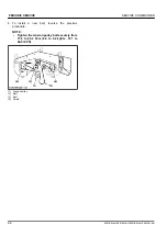
10. If at full speed the machine pulls one direction or
the other, it is an indication that one wheel is turning
faster than the other.
To adjust the condition, proceed as follows:
a. Park the machine on a firm and level surface.
b. Stop the engine.
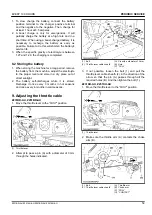
c. Loosen the 2 front bolts of the faster side.
d. Move the speed adjust plate slightly rearward.
e. Tighten the 2 front bolts securely.
Tightening torque
23.6 to 27.4 N
⋅
m
(2.4 to 2.8 kgf
⋅
m
17.4 to 20.2 lbf
⋅
ft)
2. Maximum speed (forward)
Consult your local KUBOTA Dealer for this service.
3. Motion control lever alignment
WARNING
To avoid serious injury or death:
• Park the machine on a firm and level surface.
• Stop the engine, remove the key and apply the
parking brake.
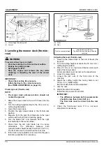
3.1 Checking the alignment
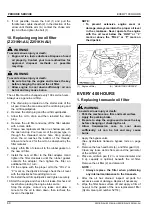
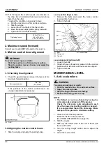
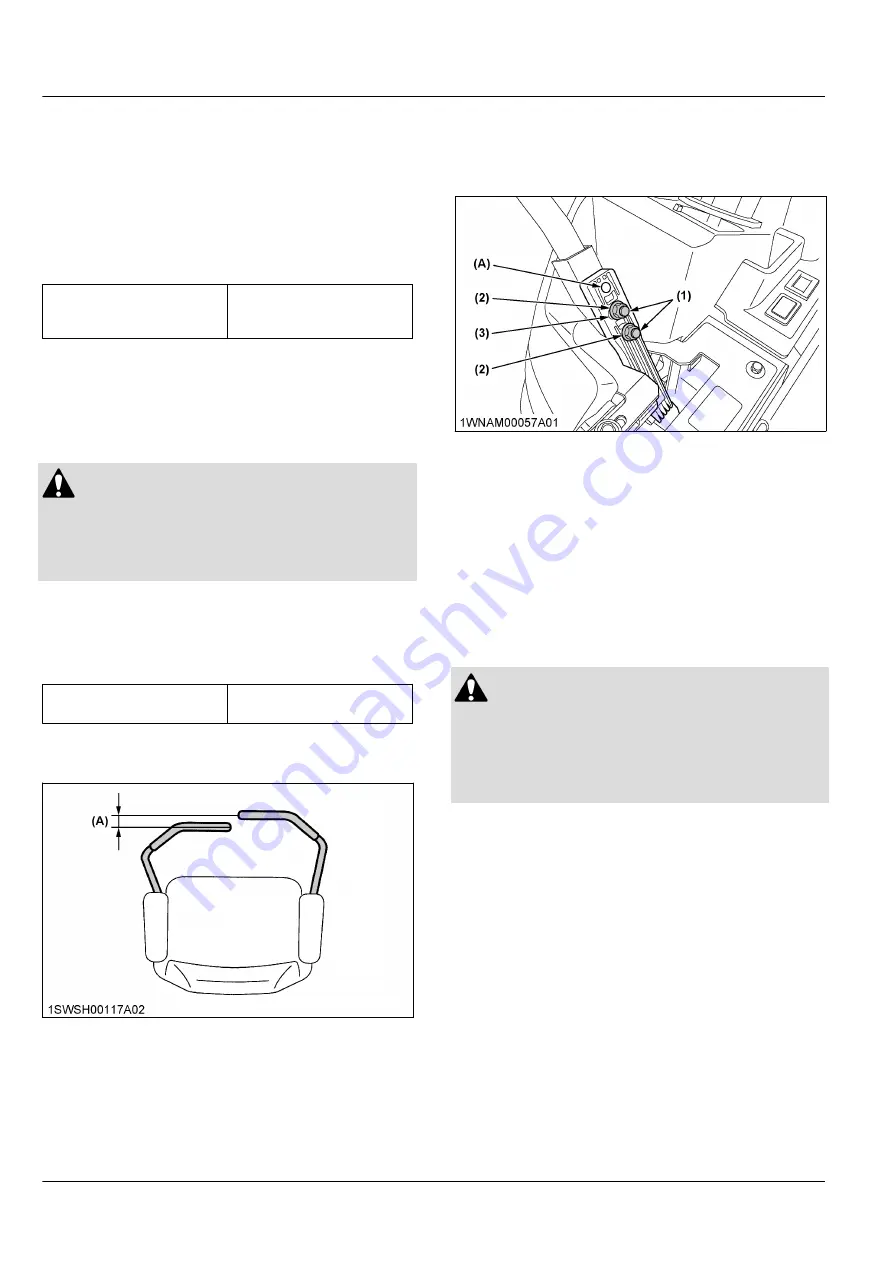
1. Check the gap and space between the levers at the
maximum forward position.
Recommended gap:
0 to 2 mm
(0 to 0.08 in.)
If the positions of the motion control levers are
unequal, adjustment is necessary.
(A) “GAP”
3.2 Aligning the motion control levers
1. Stop the engine and apply the parking brake.
Lever position (high or low)
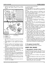
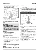
1. Remove the bolts and select the motion control
lever position, high or low.
2. Tighten the bolts.
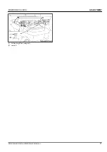
(1) Bolt
(2) Flange nut
(3) Tab slot
(A) Low position
Lever alignment (right and left)
1. Loosen the bolts.
2. Slide both levers forward or rearward to the desired
position within tab slots until the levers are aligned.
3. Tighten the bolts.
MOWER DECK LEVEL
1. Anti-scalp rollers
WARNING
To avoid serious injury or death:
• Park the machine on a firm and level surface.
• Apply the parking brake.
• Stop the engine and remove the key.
• Wait for all moving parts to stop.
NOTE :
• The flattest cut can be achieved by having the
anti-scalp rollers adjusted off the ground.
Check the anti-scalp roller adjustments each
time the mower deck cutting height is changed.
It is recommended that all the anti-scalp rollers
be kept off the ground to minimize scuffing.
1. Check the machine tire pressure.
Inflate tires to the correct pressure.
(See TIRES AND WHEELS on page 38.)
2. Start the engine.
3. Raise up the mower deck to the end of travel (the
top end of the lift).
4. Turn the cutting height control dial to adjust the
height.
5. Lower the mower deck.
ADJUSTMENT
MOTION CONTROL LEVER
68
Z231BR-AU,Z231KH-AU,Z251BR-AU,Z251KH-AU
Содержание Z231BR-AU
Страница 7: ...4 Z231BR AU Z231KH AU Z251BR AU Z251KH AU ...
Страница 13: ...SAFETY LABELS SAFE OPERATION 10 Z231BR AU Z231KH AU Z251BR AU Z251KH AU ...
Страница 14: ...SAFE OPERATION Z231BR AU Z231KH AU Z251BR AU Z251KH AU 11 ...
Страница 15: ...SAFE OPERATION 12 Z231BR AU Z231KH AU Z251BR AU Z251KH AU ...
Страница 16: ...SAFE OPERATION Z231BR AU Z231KH AU Z251BR AU Z251KH AU 13 ...
Страница 85: ...wheels 38 82 Z231BR AU Z231KH AU Z251BR AU Z251KH AU ...

