


Rev. Date: 3/14/18
Page 17
MODEL #500
General Maintenance (cont.)
SPROCKETS:
CHECK SPROCKETS FOR WEAR. Misalignment and/or loose sprockets and improper chain tension causes the premature
wear of chain and sprockets. All sprockets, except speed reducer and idler sprockets, have been secured with a medium
grade Loctite (general purpose thread locker), to prevent gradual movement. The set screws and key are also inserted with a
medium grade Loctite. If sprocket is difficult to remove, it may be heated with a propane torch to loosen.
Caution:
Do not overheat sprocket or damage to bearing will result. A pulley or bearing puller can then be used to
remove the sprocket and key. Replace new sprocket on shaft with key and medium grade Loctite applied to shaft.
Align sprocket with corresponding sprocket, using a straightedge placed along face of teeth and tighten set screw.
BEARINGS:
AGITATOR BEARINGS in hopper are prelubricated, double-sealed, self aligning ball bearings.
No
lubrication is necessary. If
bearings produce noise or heat
(too-hot-to-touch)
, the bearings should be replaced.
AGITATOR BEARING REPLACEMENT: Spray area with rust penetrant (WD-40). Remove sprocket (See SPROCKET
section above). Remove the two bolts from bearing flange and outer flange from bearing insert. Loosen set screws on bearing
hub at each end of agitator shaft. Since all set screws are installed with a medium grade Locktite, a propane hand torch may
be used to assist in removing them. Do not overheat unit, causing shaft to expand. Using a rubber mallet, drive agitator shaft
an inch in one direction, creating a space between hopper and bearing unit. A bearing puller can then be used to remove the
bearing. Eliminate any metal burrs from shaft with file and install new bearings with felt seals. Use a medium grade Loctite
on set screws before securing bearing to shaft. (Check shaft diameter before ordering bearings; 3/4" or 1")
AIRLOCK AND SHREDDER BEARINGS are prelubricated, double sealed, self aligning ball bearings. Lubrication
is
required
at three month intervals of normal running time, or sooner if bearings produce a noise or become
too-hot-to-touch
.
Relubrication at the grease fittings is done with a lithium base grease conforming to a NLGI GRADE TWO consistency. The
grease should be pumped in slowly until a slight bead forms around the seals. This bead, in addition to acting as an indicator
of adequate lubrication, provides additional protection against the entry of foreign matter.
Important:
If a slight bead does
not
form, indicating a failure of lubrication, or if bearing shows signs of wear, replace bearing.
AIRLOCK AND SHREDDER BEARING REPLACEMENT: Remove four bolts from airlock bearing flange (two bolts from
shredder bearing flange) and follow steps above for agitator bearing replacement.
SPEED REDUCER:
Periodically check oil level in reducer. Do not lay machine on its side as lubricant will drain from vent plug. If speed reducer
malfunctions because of improper oil level or type used,
warranty is voided.
Oil seals at input and output drives are
considered to be replaceable maintenance items and can affect oil level. These are available at power transmission suppliers.
LUBRICATION: This speed reducer was filled with oil at the factory to operate 30
O
F to +125
O
F ambient temperature.
After 1500 hours of operation, drain and refill with Klubersynth UH1 6-460 gear oil. If Klubersynth UH1 6-460 gear oil is not
available, use multipurpose gear oil SAE #90 for ambient temperatures from +40
O
F to +120
O
F. For temperatures below +40
O
F
use SAE #80 multipurpose gear oil. Correct oil level for mounted unit is just below pipe plug (C on illustration P) in side
position.
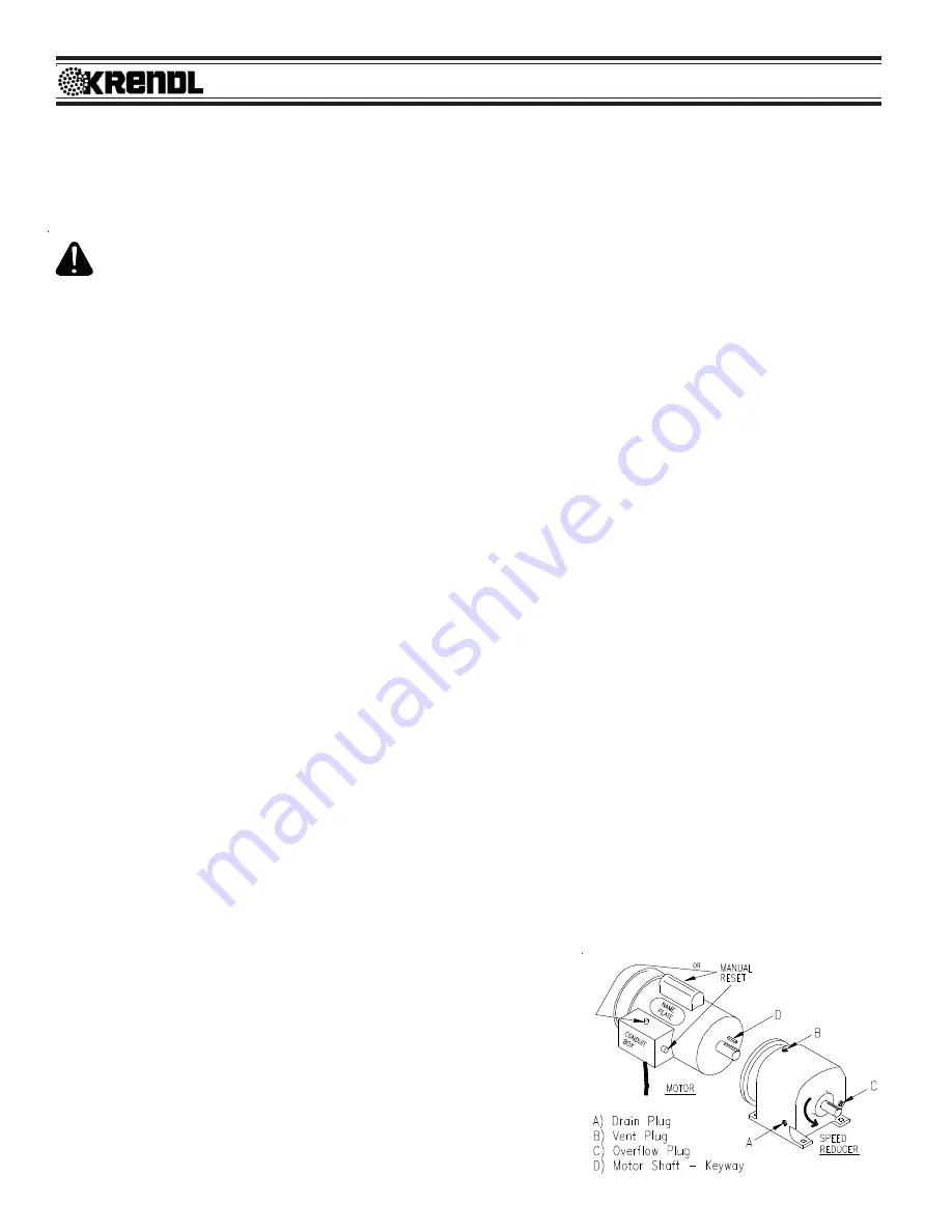
LUBRICANT REPLACEMENT: (See illustration P)
1. Drain: With output shaft of speed reducer facing you, remove plug
(A) lower front with 1/4" hex key wrench. Allow unit to completely
drain and replace plug.
2. Remove vent plug (B) on top of reducer, and plug (C) on left side.
3. Fill with recommended lubricant (use Mobilgear 630 gear oil)
through vent plug (B) opening, using a flexible funnel, until lubricant
exits the left side opening (C). (Make sure speed reducer is level
when replacing lubricant.)
4. Replace vent plug (B) and left plug (C).
(illustration P)
Содержание 500
Страница 37: ...Rev Date 3 14 18 Page34 MODEL 500 NON SHREDDER UPPER HOPPER and LOWER BASE UNIT ASSEMBLY ...
Страница 40: ...Rev Date 3 14 18 Page37 MODEL 500 SHREDDER UPPER HOPPER and LOWER BASE UNIT ASSEMBLY ...
Страница 43: ...Rev Date 3 14 18 Page40 MODEL 500 BLOWER BOX ASSEMBLY ...
Страница 45: ...Rev Date 3 14 18 Page42 MODEL 500 MECHANICAL and ELECTRICAL CONTROL ASSEMBLY OPTIONS ...
Страница 47: ...Rev Date 3 14 18 Page44 MODEL 500 OPTIONALSHREDDERASSEMBLY HOPPEREXTENSION ...
Страница 58: ...Rev Date 3 14 18 Page55 MODEL 500 SERVICE RECORD DATE MAINTENANCE PERFORMED COMPONENTS REQUIRED ...