background image


Front Panel 

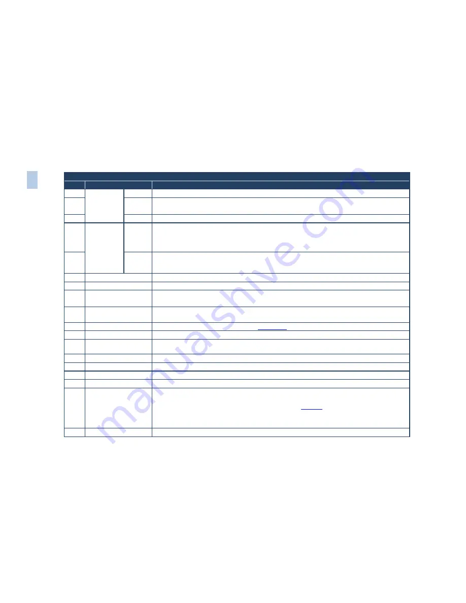
Feature 

 Function 

HDMI


Selects one of the HDMI sources (from 1 to 4) 

USB


Press to select the USB source 

JPEG files on a USB memory stick, up to a maximum size of 2048x1536 

COMP


Selects one of the component video sources (from 1 to 4) 

MODE 

SELECT 

BUTTONS 

VIDEO 

GROUP 

Select the Video Group operation mode; within each group, select which input (from 1 to 4) to switch to 

the output. The selected input button within each group is illuminated. If the AUDIO GROUP button is 

also illuminated, the audio follows the video 

When selected, this button illuminates 

SCALER 

Select the Scaler mode: press an input button (1 of 21), to select the input to be scaled at the SCALED 

OUTPUTS. The selected input button illuminates. If the MASTER AUDIO button is also illuminated, the 

audio follows the video 

LCD Status Display 

Displays the status 

10 

POWER 

Switch 

Illuminated switch for turning the unit ON or OFF 

11 

IR Receiver/LED 

Green when ON; red when OFF 

OFF in this case means that the outputs and the front-panel are disabled 

12 

FREEZE

 Button 

Freezes the output video image 

Applicable to the Scaler outputs only 

13 

PIP

 Button 

Selects the picture-in-picture function (see 

Section  6.2 

14 

MENU

 Button 

Displays the OSD Menu screen (or returns to the previous level in the OSD screen) 

15 

ENTER

 Button 

Moves to the next level in the OSD screen 

Press for about 3 seconds to lock/unlock the front panel buttons 

16 

UP

 Button 

Moves up one step (in the same level) in the OSD screen 

17 

- Button 

Decreases the range by one step 

18 

DOWN

 Button 

Moves down one step (in the same level) in the OSD screen 

19 

+ Button 

Increases the range by one step 

20 

OSD ON 

Button 

Activates/deactivates access to the OSD Menu 

The OSD ON front panel button is activated (illuminated) by default, and pressing the MENU front panel button 

(or the MENU key on the infrared remote control transmitter (see 

Figure 22

)) displays the OSD Menu. To 

prevent OSD display, press the OSD ON front panel button (or the OSD key). The front panel button no longer 

illuminates, and the front panel LCD now operates independently of the OSD (when the OSD is OFF, the LCD is 

still operational) 

21 

USB

 Connector 

Connect to a USB drive to read JPEG files 

VP

-72

5N

 –

 O

ver

vi

ew


Содержание VP-725N

Страница 1: ...KRAMER ELECTRONICS LTD USER MANUAL MODEL VP 725N Presentation Switcher Scaler P N 2900 000738 Rev 3...

Страница 2: ......

Страница 3: ......

Страница 4: ...5N via the ETHERNET port 16 6 Operating the VP 725N Presentation Switcher Scaler 18 6 1 Switching an Input in the Video Group Mode Scaler Mode 18 6 2 Understanding the PIP Feature 19 6 3 Locking and U...

Страница 5: ...igure 7 Internet Protocol TCP IP Properties Window 17 Figure 8 MENU Items 21 Figure 9 Input Screen 22 Figure 10 Picture Screen 23 Figure 11 Output Screen 24 Figure 12 PIP Screen 27 Figure 13 Geometry...

Страница 6: ...tchers GROUP 3 Control Systems GROUP 4 Format Standards Converters GROUP 5 Range Extenders and Repeaters GROUP 6 Specialty AV Products GROUP 7 Scan Converters and Scalers GROUP 8 Cables and Connectors...

Страница 7: ...com to check for up to date user manuals application programs and to check if firmware upgrades are available where appropriate 2 1 Achieving the Best Performance To achieve the best performance Use...

Страница 8: ...rame rate of a converted movie 24 frames per second to video frequencies 25 frames per second PAL 30 frames per second NTSC HDTV Compatibility and HDCP compliance The HDCP High Definition Content Prot...

Страница 9: ...rd letterbox follow output virtual wide follow input and user definable settings six switchers in one Five 4x1 dedicated signal format switchers 4x1 composite 4x1 s Video Y C 4x1 component RGB YUV 4x1...

Страница 10: ...nected to the display s source The EDID enables the VP 725N to know what kind of monitor is connected to the output The EDID includes the manufacturer s name the product type the timing data supported...

Страница 11: ...requirements Benefits consumers by providing superior uncompressed digital video quality via a single cable and user friendly connector HDMI provides the quality and functionality of a digital interfa...

Страница 12: ...defines the VP 725N Figure 1 VP 725N Presentation Switcher Scaler Front Panel Front Panel Feature Function 1 INPUT SELECTOR Buttons YC Selects one of the s Video Y C sources from 1 to 4 2 CV Selects...

Страница 13: ...front panel are disabled 12 FREEZE Button Freezes the output video image Applicable to the Scaler outputs only 13 PIP Button Selects the picture in picture function see Section 6 2 14 MENU Button Disp...

Страница 14: ...4 2 CV OUT BNC Connector Connects to the composite video acceptor 3 YC IN 4 pin Connectors Connects to the s Video Y C sources from 1 to 4 4 YC OUT 4 pin Connector Connects to the s Video Y C accepto...

Страница 15: ...nterface graphics sources from 1 to 4 15 UXGA OUT 15 pin HD Connector Connects to the UXGA analog interface graphics acceptor 16 HDMI IN Connectors Connects to the HDMI sources from 1 to 4 17 HDMI OUT...

Страница 16: ...VP 725N Installing in a Rack 11 4 Installing in a Rack This section provides instructions for rack mounting the unit...

Страница 17: ...ch off the power to each device before connecting it to your VP 725N After connecting your VP 725N connect its power and then switch on the power to each device 1 Connect one or more of the following...

Страница 18: ...ive component video inputs on the LCD monitor 5 Connect up to three SCALED OUTPUTS as follows Connect the RGBHV connectors G Y B Pb R Pr H and V to the RGBHV acceptor for example a projector Connect t...

Страница 19: ...14 VP 725N Connecting the VP 725N Presentation Switcher Scaler Figure 3 Connecting the VP 725N Presentation Switcher Scaler...

Страница 20: ...YUV YPbPr Green sync to Y Blue to Pb Red to Pr 5 3 Connecting to the VP 725N via RS 232 You can connect to the unit via a crossed RS 232 connection using for example a PC A crossed cable or null mode...

Страница 21: ...an connect the VP 725N via the Ethernet using a crossover cable see Section 5 4 1 for direct connection to the PC or a straight through cable see Section 5 4 2 for connection via a network hub or netw...

Страница 22: ...dress and fill in the details as shown in Figure 7 This IP address is compatible with the factory default IP address of the unit Figure 7 Internet Protocol TCP IP Properties Window 6 Click OK 5 4 2 Co...

Страница 23: ...nel buttons see Section 6 3 Freeze the image see Section 6 4 Display a blank screen see Section 6 5 6 1 Switching an Input in the Video Group Mode Scaler Mode The VP 725N can operate in two different...

Страница 24: ...is not connected In this case the PIP appears over a blank screen PIP Source VIDEO GRAPHIC Main Source CV YC VGA HDMI COMP CV No No Yes Yes Yes YC No No Yes Yes Yes VGA Yes Yes No No No HDMI Yes Yes...

Страница 25: ...tons lock except for the ENTER button on the front panel Operation via the infrared remote transmitter or RS 232 serial commands remote controller or PC and or ETHERNET is still available The LCD disp...

Страница 26: ...e remote transmitter To use the OSD menus 1 Select the desired input signal 2 Use the menu buttons as follows To display the main MENU screen with eight interactive icons see Figure 8 press the MENU b...

Страница 27: ...ected Supports JPEG format only The JPEG file should not exceed a resolution of 2048x1536 If the image file is not within the definition a blank screen appears and the machine displays the message Fil...

Страница 28: ...the film mode Auto Video Film Auto Temporal NR You do not have to press ENTER after selecting the desired parameter to change it Set the temporal noise reduction level Off Low Medium High High Mosqui...

Страница 29: ...66x768x60Hz 1400x1050x50Hz 1400x1050x60Hz 1600x1200x50Hz 1600x1200x60Hz 1680x1050x60Hz 1920x1080x60Hz 1920x1200x60Hz 480px60Hz 576px60Hz 720px50Hz 720px60Hz 1080ix50Hz 1080ix60Hz 1080px50Hz 1080px60Hz...

Страница 30: ...aspect ratio 0 V Pan Vertical pan 16 to 16 Available when selecting Custom aspect ratio 0 H Zoom Horizontal zoom 8 to 8 Available when selecting Custom aspect ratio 0 V Zoom Vertical zoom 8 to 8 Avai...

Страница 31: ...e top and bottom edges of the input signal but fills the width of the screen FOLLOW OUTPUT The aspect ratio and resolution of the input signal is re sized to precisely match the aspect ratio and resol...

Страница 32: ...ratio Picture In Picture PIP Source Select the PIP source See the table in Section 6 1 When changing the PIP source the display fades through black PIP Size Select the PIP size 1 25 1 16 1 9 1 4 or Cu...

Страница 33: ...If the projector is located at an angle above or below the screen 0 Diagonal Projection Move the location of each corner of the display separately horizontally and vertically Top Left Top Right Bottom...

Страница 34: ...sh rate changes according to the input refresh rate Off Auto Image Automatically adjust and align the picture each time one of the UXGA inputs is selected or if the UXGA input resolution has changed M...

Страница 35: ...and set the slideshow speed via the slideshow feature To prepare a slideshow 1 Load the slideshow JPEG images to a USB memory stick The slides appear in alphabetical order JPEG files are recognized u...

Страница 36: ...lutions and refresh rate values Mode Set Functions Setting Function Selection Range Default Mode 1 Set mode 1 1400x1050x60Hz 1680x1050x60Hz 1400x1050x60Hz Mode 2 Set mode 2 1280x1024x75Hz 1280x1024x76...

Страница 37: ...or logo The capture image size may not exceed 1280x1024 Background Set the background screen color Blue Black Custom Selecting Custom will automatically bring up a custom captured screen image that ca...

Страница 38: ...matches its HDCP output to the HDCP setting of the HDMI acceptor to which it is connected This ensures smooth switching regardless of the input Follow output Overscan Allows stretching of the outputt...

Страница 39: ...orizontal active start point 296 HA Horizontal active region 1024 HP Horizontal polarity VT Vertical total 806 VW Vertical sync pulse width 6 VS Vertical active start point 35 VA Vertical active regio...

Страница 40: ...r a typical frame of video Figure 19 Active Video Functions 7 1 7 The Info Screen From the Information screen see Figure 20 you can verify the scaler source the master audio source the PIP source the...

Страница 41: ...tons as defined in Figure 21 Figure 21 Example of How to Use the LCD Display 7 3 Operating via ETHERNET Serial Port To control your VP 725N via the Ethernet Serial Port Connect the ETHERNET port of th...

Страница 42: ...off the PIP button PIP Size Toggles the PIP size SWAP Toggles between the PIP content and the parent screen content PIP Source Selects the PIP source Press the PIP Source key and then an input key Au...

Страница 43: ...te http www kramerelectronics com Running this AP with the PC connected to the VP 725N lets you display text over the screen with features including text color and speed transparency text position and...

Страница 44: ...Baud Rate 9600 to connect via the RS 232 connector Scrolling Mode Area Blank Time Sec Dropdown Box Set the blank delay time from 1 to 5 Speed Dropdown Box Set the speed at which the text moves on the...

Страница 45: ...1366x768x60Hz 1400x1050x50Hz 1400x1050x60Hz 1600x1200x50Hz 1600x1200x60Hz 1680x1050x60Hz 1920x1080 60Hz 1920x1200 60Hz Reduced blanking 480px60Hz 576px60Hz 720px50Hz 720px60Hz 1080ix50Hz 1080i 60Hz 10...

Страница 46: ...00 75 VESA 1280x1024 76 Sun 800x600 85 VESA 1280x1024 85 VESA 832x624 75 Mac16 1366x768 60 VESA 1024x768 60 VESA 1440x900 60 VESA 1024x768 70 VESA 1400x1050 60 VESA 1024x768 75 VESA 1400x1050 75 VESA...

Страница 47: ...Resolution Vertical Frequency Hz Notes Resolution Vertical Frequency Hz Notes 640x480 60 VESA 1366x768 60 VESA 640x480 75 VESA 1400x1050 50 800x600 50 1400x1050 60 VESA 800x600 60 VESA 1600x1200 50 8...

Страница 48: ...80 75 VESA 1400x1050 50 800x600 50 1400x1050 60 VESA 800x600 60 VESA 1600x1200 50 800x600 75 VESA 1600x1200 60 VESA 1024x768 50 1920x1080 60 VESA 1024x768 60 VESA 1920x1200 60 VESA 1024x768 75 VESA 16...

Страница 49: ...CR Get Command Y Control_Type Function CR Reply Z Control_Type Function Param CR Example 1 select VGA1 as video input channel Y 0 157 0 CR Z 0 157 0 CR Example 2 get selected current input channel Y...

Страница 50: ...is set according to the input mode 0 1 10 0 31 Input Phase 0 11 N A Input Auto Image 0 1 12 50 50 Picture Brightness 0 1 13 50 50 Picture Contrast 0 1 14 50 50 Picture Color 0 1 15 180 180 Picture Hu...

Страница 51: ...0Hz 17 1366x768 60Hz 18 1400x1050 50Hz 19 1400x1050 60Hz 20 1600x1200 50Hz 21 1600x1200 60Hz 22 1680x1050 60Hz 23 1920x1080 60Hz 24 1920x1200 60Hz 25 480p 60Hz 26 576p 60Hz 27 720p 50Hz 28 720p 60Hz 2...

Страница 52: ...oom V Pan 0 1 36 0 Off 1 On PIP On Off 0 1 37 0 Picture In Picture 1 Picture Picture 2 Split PIP Type 0 1 38 0 VGA1 1 VGA2 2 VGA3 3 VGA4 4 HDMI1 5 HDMI2 6 HDMI3 7 HDMI4 8 COMP1 9 COMP2 10 COMP3 11 COM...

Страница 53: ...jection Top Left H 0 1 61 2000 2000 Geometry Diagonal Projection Top Left V 0 1 62 2000 2000 Geometry Diagonal Projection Top Right H 0 1 63 2000 2000 Geometry Diagonal Projection Top Right V 0 1 64 2...

Страница 54: ...ctory Reset 1 76 N A Firmware Revision 0 1 77 0 1400x1050x60 1 1680x1050x60 Mode Set Mode 1 0 1 78 0 1280x1024x75 1 1280x1024x76 Mode Set Mode 2 0 1 79 0 Center 1 Top Left 2 Top Right 3 Bottom Left 4...

Страница 55: ...640x480 60 1 640x480 67 Mac13 2 640x480 72 3 640x480 75 4 640x480 85 5 720x400 70 6 720x400 85 7 800x600 56 8 800x600 60 9 800x600 72 10 800x60075 11 800x600 85 12 832x62475 Mac16 13 1024x768 60 14 10...

Страница 56: ...8 60 55 1366x768 60 R 94 Custom1 95 Custom2 96 Custom3 97 Custom4 98 No Input detected 99 other 101 NTSC 102 PAL 103 PAL M 104 PAL N 105 NTSC 4 43 106 SECAM 107 PAL 60 1 104 0 640x480 60 1 640x480 67...

Страница 57: ...60 47 1280x720 60 48 1080p 24 49 1280x800 60 50 1440x900 60 51 1440x900 60 R 52 1280x768 60 R 53 1680x1050 60 R 54 1366x768 60 55 1366x768 60 R 94 Custom1 95 Custom2 96 Custom3 97 Custom4 98 No Input...

Страница 58: ...tput Mode VT 0 1 125 2 HS 13 Advance Output Mode VW 0 1 126 15 VT VA 1 Advance Output Mode VS 0 1 127 480 1200 VT 16 Advance Output Mode VA 0 1 128 0 Negative polarity 1 Positive polarity Advance Outp...

Страница 59: ...2 2 Parameter 4 7 for getting HDMI Group 2 3 Parameter 8 11 for getting COMP Group 2 4 Parameter 12 15 for getting YC Group 2 5 Parameter 16 19 for getting CV Group 2 6 Parameter 20 or others are unav...

Страница 60: ...I monitor s EDID 0 1 206 0 Off 1 On HDMI1 Input HDCP setting 0 1 207 0 Off 1 On HDMI2 Input HDCP setting 0 1 208 0 Off 1 On HDMI3 Input HDCP setting 0 1 209 0 Off 1 On HDMI4 Input HDCP setting 0 1 210...

Страница 61: ...56 VP 725N...

Страница 62: ...ributors visit our Web site where updates to this user manual may be found We welcome your questions comments and feedback Web site www kramerelectronics com E mail info kramerel com SAFETY WARNING Di...

Отзывы: