background image


30 


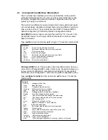
Summary of the 5 command modes. 


Command 

Mode 

Main Function 

Enter and Exit Method 

Prompt 

User EXEC


This is the first level of access. 

User can ping, telnet remote 

device, and show some basic 

information


Enter:

 Login

 successfully


Exit: 

exit 

to logout. 

Next mode: Type 

enable

 to 

enter privileged EXEC mode.

Switch> 


Privileged 

EXEC


In this mode, the system allows 

you to view current configuration, 

reset default, reload switch, show 

system information, save 

configuration…and enter global 

configuration mode.


Enter: Type 

enable

 in User 

EXEC mode. 

Exec: Type 

disable

 to exit to 

user EXEC mode. 

Type 

exit

 to logout 

Next Mode: Type 

configure 

terminal 

to enter global 

configuration


command.


Switch# 


Global 

configuration


In global configuration mode, you 

can configure all the features that

the system provides you


Enter: Type 

configure 

terminal

 in privileged EXEC 

mode 

Exit: Type 

exit 

or 

end 

or press 

Ctrl-Z 

to exit. 

Next mode: Type 

interface 

IFNAME/ VLAN VID

 to enter 

interface configuration mode


Switch(config)# 


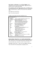
Port 

Interface 

configuration


In this mode, you can configure 

port related settings.


Enter: Type 

interface IFNAME

in global configuration mode. 

Exit: Type 

exit

 or 

Ctrl+Z

 to 

global configuration mode. 

Switch(config-if)# 


Switch(config)# interface vlan 1
Switch(config-if)# 
  description  Interface specific description 
  end          End current mode and change to enable mode 
  exit         Exit current mode and down to previous mode 
  ip           Interface Internet Protocol config commands 
  list         Print command list 
  no           Negate a command or set its defaults 
  quit         Exit current mode and down to previous mode 
  shutdown     Shutdown the selected interface 

Содержание JetNet 6710G

Страница 1: ...1 Korenix JetNet 6710G Series Industrial 8 Port PoE 2 Gigabit TX Managed Ethernet Switch User Manual Ver 05 Jun 2011 Firmware v1 0a www korenix com ...

Страница 2: ...ies Industrial 8 Port PoE 2 Gigabit TX Managed Ethernet Switch User s Manual Copyright Notice Copyright 2010 Korenix Technology Co Ltd All rights reserved Reproduction in any form or by any means without permission is prohibited ...

Страница 3: ...s equipment generates uses and can radiate radio frequency energy and if not installed and used in accordance with the instruction manual may cause harmful interference to radio communications Operation of this equipment in a residential area is likely to cause harmful interference in which case the user will be required to correct the interference at his expense The user is cautioned that changes...

Страница 4: ...2 Preparation for Web Interface 20 3 3 Preparation for Telnet Console 23 4 Feature Configuration 26 4 1 Command Line Interface Introduction 27 4 2 Basic Setting 33 4 3 Port Configuration 53 4 4 Power over Ethernet 61 4 5 Network Redundancy 70 4 6 VLAN 81 4 7 Traffic Prioritization 91 4 8 Multicast Filtering 97 4 9 SNMP 102 4 10 Security 106 4 11 Warning 113 4 13 Monitor and Diag 124 4 14 Device Fr...

Страница 5: ...d security features The Network control feature allows user to optimize the industrial network environment The supported features include VLAN IGMP Snooping Quality of Service QoS Link Aggregation Control Protocol LACP Rate Control The security also helps users to avoid hacker s attack The features included are DHCP client DHCP server with IP and MAC binding 802 1X Access Control SSH for Telnet se...

Страница 6: ... series to meet the network needs without compromising the speed of the network The MSRTM also facilitates the JetNet series to connect with coe management switch vi standard rapid spanning tree protocol or through multiple paths or nodes to increase the reliability by RDHTM Rapid Dual Homing RDHTM technology By integrating MSRTM and Link Aggregation Control Protocol LACP the JetNet series can enh...

Страница 7: ... static trunk or LACP Not all the link sections in a TrunkRing need to be the same Ring links can be either symmetric or asymmetric Some are a single path and the others are aggregated by links where the number of links in a trunk group can be different Users can enhance the link redundancy at different locations in accordance to the need And the link with less speed is more likely to be used as t...

Страница 8: ...lso delivers group IP assignment firmware upgrade configuration files backup restore SNMP MIB Broswer compile MSRTM group management and also allows user to exports topology map to drawing file JPEG BMP PNG or PDF for other application 1 2 Major Features Korenix JetNet 6710G Series products have the following features 8 10 100 Base TX and 2 Gigabit ports Rugged M12 RJ 45 Ethernet Connector 8 port ...

Страница 9: ...12 Rugged RJ 1 1 JetNet 6810 Managed Booster PoE Switch M12 Rugged RJ 1 1 M12 on DB9 Shielded Console Cable 1 1 1 1 Rugged M12 D coded 4 pole Field Assemble able Connecter 8 8 Rugged M12 A coded 8 pole Field Assemble able Connector 2 2 Rugged RJ45 Field Assemble able Connecter 10 10 2 Wall Mount kits 8 Screws 1 1 1 1 Quick Installation Guide 1 1 1 1 Documentation and Software CD ROM 1 1 1 1 If any...

Страница 10: ...ion and configuration information Following topics are covered in this chapter 2 1 Hardware Introduction Dimension Panel Layout Bottom View 2 2 Wiring Power Inputs 2 3 RS 232 console and relay output 2 4 Wiring Earth ground 2 5 Wiring Ethernet Ports 2 6 Wall mounting Installation ...

Страница 11: ...7 2 1 Hardware Introduction Dimension JetNet 6710G s dimension W x H x D is 96mm x 137mm x 119mm JetNet 6710G m12 JetNet 6710G RJ ...

Страница 12: ...8 Panel Layout The front panel includes 10 100Mbps PoE ports Gigabit Ethernet ports RS232 console with DO port System Port LED and Power input ...

Страница 13: ...nput AWG No Cable Area mm 2 JetNet 6710G M12 48 60 48 V1 V2 AWG 14 2 0 JetNet 6710G RJ 48 60 48 V1 V2 AWG 14 2 0 JetNet 6810G M12 22 60 24 V1 V2 bind together AWG 14 2 0 JetNet 6810G RJ 22 60 24 V1 V2 bind together AWG 14 2 0 Table 2 Power Input Voltage The JetNet 6810G only supports single power input that binds V1 and V2 together to obtain higher current for the booster Use the UL listed Switchi...

Страница 14: ...10 Figure 2 2 2 Power connector assembly diagram ...

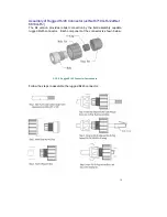
Страница 15: ...the parts 1 2 3 are already assembled Follow the steps for soldering and assembling the cable and connector together Step 1 Slide component 4 5 6 and then 7 over the console cable Keep them loose Do not tighten them yet 2 cable glands are provided for cable diameter from 3 5 to 5 8 mm Choose the one that best fits the cable Picture 8 Step 2 Solder the conductors with the copper wires according to ...

Страница 16: ...3 Fasten the components 4 5 6 and 7 in sequence Be sure the gasket is on the right position See the below M12 assembly diagram Picture 10 M12 Assembly 2 4 Wiring Earth Ground To ensure the system will not be damaged by noise or any electrical shock ...

Страница 17: ...rew after earth ground wire is connected 2 5 Wiring Fast Ethernet Ports You can connect terminal devices and other segments via twisted pair cables Ports which are not assigned should be closed with the covering caps contained in the package list of delivery to guarantee the connector is clear without rust Never install or work on with the equipment or the cabling during the period of its lightinn...

Страница 18: ... TX 4 M12 M12 MDI X 1 TX RX 2 2 RX TX 1 3 TX RX 4 4 RX TX 3 Picture 14 M12 to M12 Ethernet Cable Wiring For Fast Ethernet M12 D Code to RJ45 connection the pin assignment of the patch cable is shown below M12 RJ45 MDI 1 T X R X 3 2 R X T X 1 3 T X R X 6 4 R X T X 2 M12 RJ45 MDI X 1 T X R X 1 2 R X T X 3 3 T X R X 2 4 R X T X 6 Picture 15 M12 to RJ45 Ethernet Cable Wiring ...

Страница 19: ...15 For Gigabit Ethernet M12 A Code to RJ45 connection the pin assignment of the patch cable is shown below Picture 16 Gigabit M12 to RJ45 Ethernet Cable Wiring ...

Страница 20: ...version provides robust connection by the field assembly capable rugged RJ45 connector Each component of the connector is shown below 3 3 2 1 Rugged RJ45 Connecter Components Follow the steps to assemble the rugged RJ45 connector Picture 18 Rugged RJ45 Cable Connection diagram ...

Страница 21: ...le based on the two standards released by TIA EIA 568A and 568B The 568B wiring is by far the most common wiring method You can choose the method that suits your application but ensure that both ends of the cable use the same standard Picture 19 RJ45 Cable color code ...

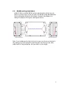
Страница 22: ...10G JetNet 6810G for the mounting plate fixate Use the screws included in the shipment to locking the plates as the figure A and figure B below Note To avoid damage the internal circuit be sure use the screw included in the package to screw and tight the wall mount kit onto the rear side of the JetNet switch The specification of screw is M3 in 6 mm length ...

Страница 23: ...ation for Web Interface 3 3 Preparation for Telnet console 3 1 Preparation for Serial Console In JetNet 6710G JetNet 6810G package Korenix attached one M12 to RS 232 DB 9 console cable Please attach RS 232 DB 9 connector to your PC COM port connects M12 to the Console port of the JetNet 6710G If you lose the cable please follow the console cable PIN assignment to find one Refer to the appendix 1 G...

Страница 24: ...switch via the web browser 1 Verify that your network interface card NIC is operational and that your operating system supports TCP IP protocol 2 Wire DC power to the switch and connect your switch to your computer 3 Make sure that the switch default IP address is 192 168 10 1 4 Change your computer IP address to 192 168 10 2 or other IP address which is located in the 192 168 10 x Network Mask 25...

Страница 25: ...fault Users have to directly modify the browser settings to selectively enable Java applets to use network ports Note 2 The Web UI connection session of JetNet 6710G JetNet 6810G will be logged out automatically if you don t give any input after 30 seconds After logged out you should re login and key in correct user name and password again 3 2 2 Secured Web Interface Korenix web management page al...

Страница 26: ...e popup screen will appear and request you to trust the secured HTTPS connection distributed by JetNet 6710G first Press Yes to trust it 4 The login screen will appear next 5 Key in the user name and the password The default user name and password is admin 6 Click on Enter or OK Welcome page of the web based management interface will then appear 7 Once you enter the web based management interface ...

Страница 27: ...nfiguration commands you sent to the switch SSH is a client server architecture while the Switch is the SSH server When you want to make SSH connection with the switch you should download the SSH client tool first SSH Client There are many free sharewares trials or charged SSH clients you can find on the internet Fox example PuTTY is a free and popular Telnet SSH client We ll use this tool to demo...

Страница 28: ...24 2 After click on Open then you can see the cipher information in the popup screen Press Yes to accept the Security Alert ...

Страница 29: ...elow figure sample of JetNet 5010G 4 Type the Login Name and its Password The default Login Name and Password are admin admin 5 All the commands you see in SSH are the same as the CLI commands you see via RS232 console The next chapter will introduce in detail how to use command line to configure the switch ...

Страница 30: ... You just need to know the device s IP address Then you can remotely connect to its embedded HTML web pages or Telnet console Korenix web management page is developed by JAVA It allows you to use a standard web browser such as Microsoft Internet Explorer or Mozila to configure and interrogate the switch from anywhere on the network Note IE 5 0 or later versions do not allow Java applets to open so...

Страница 31: ...l configuration mode Type configure terminal to enter next mode exit to leave to see the command list JN6710G enable Turn on privileged mode command exit Exit current mode and down to previous mode list Print command list ping Send echo messages quit Exit current mode and down to previous mode show Show running system information telnet Open a telnet connection traceroute Trace route to destinatio...

Страница 32: ...n to previous mode gmrp GMRP protocol gvrp GARP VLAN Registration Protocol hostname Set system s network name interface Select an interface to configure ip IP information lacp Link Aggregation Control Protocol list Print command list lldp Link Layer Discovery Protocol log Logging control mac address table mac address table mirror Port mirroring multiple super ring Configure Multiple Super Ring nam...

Страница 33: ...erface fa1 Switch config if acceptable Configures the 802 1Q acceptable frame types of a port auto negotiation Enables auto negotiation state of a given port description Interface specific description dot1x IEEE 802 1x standard access security control duplex Specifies the duplex mode of operation for a port end End current mode and change to enable mode exit Exit current mode and down to previous ...

Страница 34: ...ation In global configuration mode you can configure all the features that the system provides you Enter Type configure terminal in privileged EXEC mode Exit Type exit or end or press Ctrl Z to exit Next mode Type interface IFNAME VLAN VID to enter interface configuration mode Switch config Port Interface configuration In this mode you can configure port related settings Enter Type interface IFNAM...

Страница 35: ...terface Configuration In this mode you can configure settings for specific VLAN Enter Type interface VLAN VID in global configuration mode Exit Type exit or Ctrl Z to global configuration mode Type end to privileged EXEC mode Switch config vlan ...

Страница 36: ...ommand Ctrl S To lock the screen of the terminal You can t input any command Ctrl Q To unlock the screen which is locked by Ctrl S Ctrl Z To exit configuration mode Alert message when multiple users want to configure the switch If the administrator is in configuration mode then the Web users can t change the settings JetNet Managed Switch allows only one administrator to configure the switch at a ...

Страница 37: ...erver 4 2 6 Backup and Restore 4 2 7 Firmware Upgrade 4 2 8 Factory Default 4 2 9 System Reboot 4 2 10 CLI Commands for Basic Setting 4 2 1 Switch Basic Setting You can assign System name Location Contact and view system information Below Figure 4 2 1 1 Web UI of the Switch Basic Setting System Name You can assign a name to the device The available characters you can input is 64 After you configur...

Страница 38: ...in this device MAC Address Display unique hardware address MAC address assigned by the manufacturer Once you finish the configuration click on Apply to apply your settings Note Always remember to select Save to save your settings Otherwise the settings you made will be lost when the switch is powered off 4 2 2 Admin Password You can change the user name and the password here to enhance security Fi...

Страница 39: ...ult IP address will therefore be replaced by the one assigned by DHCP server If DHCP Client is disabled then the IP address that you specified will be used instead IP Address You can assign the IP address reserved by your network for your JetNet If DHCP Client function is enabled you don t need to assign an IP address to the JetNet as it will be overwritten by DHCP server and shown here The defaul...

Страница 40: ...configuration 4 2 4 Time Setting Time Setting source allow user to set the time manually or through NTP server Network Time Protocol NTP is used to synchronize computer clocks on the internet You can configure NTP settings here to synchronize the clocks of several switches on the network Below figure is similar as JetNet 6710G Manual Setting User can select Manual setting to change time as user wa...

Страница 41: ...zed the system time will display the correct time of the PTP server Time zone Select the time zone where the switch is located Following table lists the time zones for different locations for your reference The default time zone is GMT Greenwich Mean Time Switch config clock timezone 01 GMT 12 00 Eniwetok Kwajalein 02 GMT 11 00 Midway Island Samoa 03 GMT 10 00 Hawaii 04 GMT 09 00 Alaska 05 GMT 08 ...

Страница 42: ...nsk 33 GMT 02 00 Bucharest 34 GMT 02 00 Cairo 35 GMT 02 00 Harare Pretoria 36 GMT 02 00 Helsinki Riga Tallinn 37 GMT 02 00 Jerusalem 38 GMT 03 00 Baghdad 39 GMT 03 00 Kuwait Riyadh 40 GMT 03 00 Moscow St Petersburg Volgograd 41 GMT 03 00 Nairobi 42 GMT 03 30 Tehran 43 GMT 04 00 Abu Dhabi Muscat 44 GMT 04 00 Baku Tbilisi Yerevan 45 GMT 04 30 Kabul 46 GMT 05 00 Ekaterinburg 47 GMT 05 00 Islamabad Ka...

Страница 43: ...me Set the daylight saving time summer time start and end time The daylight saving configuration is based on the week and monthly with hour and minute setting Once you finish your configuration click on Apply to apply your configuration 4 2 5 DHCP Server You can select to Enable or Disable DHCP Server function JetNet switch will assign a new IP address to link partners DHCP Server configuration Af...

Страница 44: ... to the network device Add or remove an IP address from the Excluded Address List by clicking Add or Remove Manual Binding JetNet 6710G JetNet 6810G provides a MAC address and IP address binding and removing function You can type in the specified IP and MAC address and then click Add to add a new MAC IP address binding rule for a specified link partner like PLC or any device without DHCP client fu...

Страница 45: ...ton to refresh the listing DHCP Relay Agent You can select to Enable or Disable DHCP relay agent function and then select the modification type of option 82 field Relay policy drop Drops the option 82 field and do not add any option 82 field Relay policy keep Keeps the original option 82 field and forwards to server Relay policy replace Replaces the existing option 82 field and adds new option 82 ...

Страница 46: ...is mode the switch acts as TFTP client Before you do so make sure that your TFTP server is ready Then please type the IP address of TFTP Server and Backup configuration file name This mode can be used in both CLI and Web UI TFTP Server IP Address You need to key in the IP address of your TFTP Server here Backup Restore File Name Please type the correct file name of the configuration file Configura...

Страница 47: ...up Restore Configuration Local File mode Click on Folder icon to select the target file you want to backup restore Note that the folders of the path to the target file do not allow you to input space key Figure 4 2 6 3 Backup Restore Configuration TFTP Server mode ...

Страница 48: ...al viewpoint we suggest you use the latest firmware before installing the switch to the customer site Note that the system will be automatically rebooted after you finished upgrading new firmware Please remind the attached users before you do this The similar Figure 4 2 7 1 Main UI of Firmware Upgrade for the JetNet Switch There are 2 modes for users to backup restore the configuration file Local ...

Страница 49: ...ver IP address This mode can be used in both CLI and Web UI TFTP Server IP Address You need to key in the IP address of your TFTP Server here Firmware File Name The file name of the new firmware The UI also shows you the current firmware version and built date of current firmware Please check the version number after the switch is rebooted Figure 4 2 7 2 Firmware Upgrade Local File mode Click on F...

Страница 50: ...erver and Firmware File Name Then click on Upgrade to start the process After finishing transmitting the firmware the system will copy the firmware file and replace the firmware in the flash The CLI show until the process is finished ...

Страница 51: ...ult setting will work after rebooting the switch Figure 4 2 8 1 The main screen of the Factory Default Figure 4 2 8 2 Popup alert screen to confirm the command Click on Yes to start it Figure 4 2 8 3 Popup message screen to show you that have done the command Click on OK to close the screen Then please go to Reboot page to reboot the switch Click on OK The system will then auto reboot the device N...

Страница 52: ...e Some of the feature changes require you to reboot the system Click on Reboot to reboot your device Note Remember to click on Save button to save your settings Otherwise the settings you made will be gone when the switch is powered off Figure 4 2 9 1 Main screen for Rebooting Figure 4 2 9 2 Pop up alert screen to request confirmation Click on Yes Then the switch will be rebooted immediately Figur...

Страница 53: ...05 28 Software Information Loader Version 1 0 0 4 Firmware Version 0 1 32 20100830 16 10 40 Copyright 2006 2009 Korenix Technology Co Ltd Switch Switch show hardware mac MAC Address 00 12 77 FF 01 B0 Admin Password User Name and Password SWITCH config administrator NAME Administrator account name SWITCH config administrator orwell PASSWORD Administrator account_name account_password SWITCH config ...

Страница 54: ...g clock timezone you can see the timezone list Then choose the number of the timezone you want to select IEEE 1588 Switch config ptpd run cr preferred clock Preferred Clock slave Run as slave Display SWITCH sh ntp associations Network time protocol Status Disabled Primary peer N A Secondary peer N A SWITCH show clock Sun Jan 1 04 14 19 2006 GMT Greenwich Mean Time Dublin Edinburgh Lisbon London SW...

Страница 55: ...ime Remains list leased Time remain information for each entry Backup and Restore Backup Startup Configuration file Switch copy startup config tftp 192 168 10 33 default conf Writing Configuration OK Note 1 To backup the latest startup configuration file you should save current settings to flash first You can refer to 4 12 to see how to save settings to the flash Note 2 192 168 10 33 is the TFTP s...

Страница 56: ...52 Firmware upgrade success Rebooting Factory Default Factory Default Switch reload default config file Reload OK Switch reboot System Reboot Reboot Switch reboot ...

Страница 57: ...nes for Port Configuration 4 3 1 Port Control Port Control commands allow you to enable disable port state or configure the port auto negotiation speed duplex and flow control Select the port you want to configure and make changes to the port In State column you can enable or disable the state of this port Once you disable the port stop to link to the other end and stop to forward any traffic The ...

Страница 58: ...corresponding port on the switch to work Disable means that you don t need to activate the flow control function of the remote network device as the flow control of that corresponding port on the switch will work anyway Once you finish configuring the settings click on Apply to save the configuration Technical Tips If both ends are not at the same speed they can t link with each other If both ends...

Страница 59: ...pe that you want to filter The packet types of the Ingress Rule listed here include Broadcast Only Broadcast and multicast Broadcast Multicast and Unknown Unicast or All The packet types of the Egress Rule outgoing only support all packet types Rate This column allows you to manually assign the limit rate of the port Valid values are from 1Mbps 100Mbps for fast Ethernet ports and gigabit Ethernet ...

Страница 60: ...the port trunking Different manufacturers may use different descriptions for their products like Link Aggregation Group LAG Link Aggregation Control Protocol Ethernet Trunk Ether Channel etc Most of the implementations now conform to IEEE standard 802 3ad The aggregated ports can interconnect to the other switch which also supports Port Trunking Korenix Supports 2 types of port trunking One is Sta...

Страница 61: ... status of port aggregation Once the aggregation ports are negotiated well you will see following status Group ID Display Trunk 1 to Trunk 5 set up in Aggregation Setting Type Static or LACP set up in Aggregation Setting Aggregated When LACP links well you can see the member ports in aggregated column Individual When LACP is enabled member ports of LACP group which are not connected to correct LAC...

Страница 62: ...ink Change to DOWN set the speed mode ok Switch config if Port1 Link Change to UP Switch config if duplex full Port1 Link Change to DOWN set the duplex mode ok Switch config if Port1 Link Change to UP Port Control Flow Control Switch config if flowcontrol on Flowcontrol on for port 1 set ok Switch config if flowcontrol off Flowcontrol off for port 1 set ok Port Status Port Status Switch show inter...

Страница 63: ...limit mode broadcast ok Rate Control Bandwidth Switch config if rate limit ingress bandwidth 0 100 Limit in magabits per second 0 is no limit Switch config if rate limit ingress bandwidth 8 Set the ingress rate limit 8Mbps for Port 1 Port Trunking LACP Switch config lacp group 1 gi8 10 Group 1 based on LACP 802 3ad is enabled Note The interface list is fa1 fa3 5 gi8 10 Note different speed port ca...

Страница 64: ...60 Trunk Group GroupID Protocol Ports 2 Static 6 D 7 P Switch ...

Страница 65: ...ypes in the industry application fields As a result they can be flexibly used to deliver power for different PoE enabled devices in various applications IEEE 802 3at LLDP provides smart power budget control behavior to fulfill the needs of higher end setups requiring exact high power delivery By using the ongoing dynamic re negotiation function of the IEEE802 3at LLDP the JetNet 6710G series can p...

Страница 66: ... w the power supply output ability which is installed with PoE Switch It will pop up a warning message when the PoE port setting is over the system power supply output ability Port Configuration the port configuration includes PoE mode powering mode power budget mode and power budget for each PoE ports The following is the description for each function PoE mode PoE control for the current port Pow...

Страница 67: ...4 12 5 By the port of JetNet 6710G JetNet 6810G connected to the PD ex Port 4 set PoE Mode is Enable and Powering Mode is 802 3at LLDP When JetNet 6710G JetNet 6810G and the PD are ready to IEEE802 3at LLDP IEEE 802 3at LLDP starts operation Finally see the result on Poe Status refer to 4 4 5 Note To enable the IEEE 802 3at High Power PoE function the power input voltage should be over than DC 55V...

Страница 68: ...ice The following figure shows the Web configure interface for Power over Ethernet PD Status Detection You can enable disable PD Status Detection function and type in the IP address that you want to detect The Cycle Time is the gap per detection After configuring please click the Apply button to enable and perform the functions 4 4 3 PoE Scheduling The PoE Scheduling control is a powerful function...

Страница 69: ...ge shows the operating status of each PoE Port The information includes PoE mode Operation status PD class Power Consumption Voltage and Current 4 4 5 Command Line for PoE control Syntax show poe system Parameters Command Mode Enable mode ...

Страница 70: ...t1 POE Port 1 Control Mode User Disable Powering Mode 802 3af Operation Status Off Detection Status Valid Classification N A Priority Highest Output Power 0 0 Watts Voltage 0 0 V Current 0 mA Power Budget Budget 32 0 Watts effective 0 Watts Warning water level N A Utilization 0 Event Normal Syntax show poe pd_detect Parameters Command Mode Enable mode Description Display the status of pd status de...

Страница 71: ... mode Switch config poe powering mode 802 3af EX 2 Set forced powering mode Switch config poe powering mode forced Syntax poe powering mode 802 3at 2 event lldp Parameters 2 event deliver power if and only if the attached PD comply with IEEE 802 3at physical layer classification lldp deliver power if and only if the attached PD comply with IEEE 802 3at data link layer classification Command Mode I...

Страница 72: ...of 802 3af powering mode is 15 4 The max budget of 802 3at powering mode is 32 The max budget of force powering mode is 32 Examples Set the max value of power consumption to 12 W with manual mode Switch config if poe budget 12 Syntax poe budget warning 0 100 Parameters 0 100 0 is disable valid range is 1 to 100 percentage Command Mode Interface mode Description Set the warning water level of port ...

Страница 73: ...de Configuration mode Description Set the warning water level of total power budget Examples Set the warning water level to 60 Switch config if poe budget warning 60 Syntax poe pd_detect enable disable Parameters enable enable PD Status Detection function disable disable PD Status Detection function Command Mode Configuration mode Description Enable Disable the PD Status Detection function Example...

Страница 74: ...per Ring ports can pass through Super Ring control packets extremely well and works with Super Ring Besides Korenix ring technology JetNet 6710G also supports 802 1D 2004 version Rapid Spanning Tree Protocol RSTP New version of RSTP standard includes 802 1D 1998 STP 802 1w RSTP Following commands are included in this group 4 5 1 RSTP 4 5 2 RSTP Info 4 5 3 Multiple Super Ring 4 5 4 Multiple Super R...

Страница 75: ... switch supports both RSTP and STP all switches that support RSTP are also backward compatible with switches that support only STP This page allows you to enable disable RSTP configure the global setting and port settings RSTP Mode You must first enable STP RSTP mode before configuring any related parameters Parameter settings required for both STP and RSTP are the same Note that 802 1d refers to ...

Страница 76: ... spanning tree topology Hello Time 1 10 Enter a value from 1 to 10 seconds here This is a periodic timer that drives the switch to send out BPDU Bridge Protocol Data Unit packet to check current STP status The root bridge of the spanning tree topology periodically sends out a hello message to other devices on the network to check if the topology is healthy The hello time is the amount of time the ...

Страница 77: ...ore bridges i e it is served by a shared medium LAN segment This function allows P2P status of the link to be manipulated administratively Auto means to auto select P2P or Share mode P2P means P2P is enabled while Share means P2P is disabled Admin Edge A port directly connected to the end stations cannot create a bridging loop in the network To configure this port as an edge port set the port to t...

Страница 78: ... Ring MSR The most common industrial network redundancy is to form a ring or loop Typically the managed switches are connected in series and the last switch is connected back to the first one In such connection you can implement Korenix Super Ring Rapid Super Ring and Multiple Super Ring technology Super Ring is Korenix 1st generation ring redundancy technology released with JetNet 4000 and 4500 s...

Страница 79: ...d This appears and can not be changed Name This field will show the name of the Ring If it is not filled in when creating it will be automatically named by the rule RingID Version The version of Ring can be changed here There are three modes to choose Rapid Super Ring as default Super ring for compatible with Korenix 1st general ring and Any Ring for compatible with other version of rings Device P...

Страница 80: ... is an important feature of Korenix 3rd generation Ring redundancy technology When you want to connect multiple RSR or form redundant topology with other vendors RDH could allow you to have maximum 7 multiple links for redundancy without any problem In Dual Homing I released with JetNet 4000 4500 series you have to configure additional port as Dual Homing port to two uplink switches In Rapid Dual ...

Страница 81: ...y one of the link in this Ring is broken then the status will be Abnormal RM MAC The MAC address of Ring Master of this Ring It helps to find the redundant path Blocking Port This field shows which is blocked port of RM Role Transition Count This means how many times this switch has changed its Role from nonRM to RM or from RM to nonRM Role state Transition Count This number means how many times t...

Страница 82: ...itch config if spanning tree cost 200000 Port Priority Switch config if spanning tree port priority 0 240 Number from 0 to 240 in multiple of 16 Switch config if spanning tree port priority 128 Link Type Auto Switch config if spanning tree link type auto Link Type P2P Switch config if spanning tree link type point to point Link Type Share Switch config if spanning tree link type shared Edge Port S...

Страница 83: ...e or configure a Ring Switch config multiple super ring 1 Ring 1 created Switch config multiple super ring Note 1 is the target Ring ID which is going to be created or configured Super Ring Version Switch config multiple super ring version any ring any ring auto detection default set default to rapid super ring rapid super ring rapid super ring super ring super ring Switch config multiple super ri...

Страница 84: ...or dual Homing Ring Info Ring Info Switch show multiple super ring Ring ID Ring1 Ring1 Current Status Disabled Role Disabled Ring Status Abnormal Ring Manager 0000 0000 0000 Blocking Port N A Giga Copper N A Configuration Version Rapid Super Ring Priority 128 Ring Port fa1 fa2 Path Cost 100 200 Dual Homing II Disabled Statistics Watchdog sent 0 received 0 missed 0 Link Up sent 0 received 0 Link Do...

Страница 85: ...known as Tag Based VLAN This Tag Based VLAN allows VLAN to be created across different switches see Figure 1 IEEE 802 1Q tag based VLAN makes use of VLAN control information stored in a VLAN header attached to IEEE 802 3 packet frames This tag contains a VLAN Identifier VID that indicates which VLAN a frame belongs to Since each switch only has to check a frame s tag without the need to dissect th...

Страница 86: ...erved You can t input these 2 PVIDs 1 is the default value 2 to 4094 are valid and available in this column Type the PVID you d like to configure here Accept Frame Type This column defines the accepted frame type of the port There are 2 modes you can select Admit All and Tag Only Admit All mode means that the port can accept both tagged and untagged packets Tag Only mode means that the port can on...

Страница 87: ...gement VLAN ID The switch supports management VLAN The management VLAN ID is the VLAN ID of the CPU interface so that only member ports of the management VLAN can ping and access the switch The default management VLAN ID is 1 Static VLAN You can assign a VLAN ID and VLAN Name for new VLAN here VLAN ID is used by the switch to identify different VLANs Valid VLAN ID is between 1 and 4094 1 is the de...

Страница 88: ...nt VLAN ID by Web and Telnet remember that the port attached by the administrator should be the member port of the management VLAN otherwise the administrator can t access the switch via the network Note Currently JetNet6710G only support max 256 groups VLAN Static VLAN Configuration You can see the created VLANs and specify the egress outgoing port rule to be Untagged or Tagged here Figure 4 6 2 ...

Страница 89: ...N tagged T Tag Indicates that egress outgoing frames are to be VLAN tagged Steps to configure Egress rules Select the VLAN ID Entry of the selected VLAN turns to light blue Assign Egress rule of the ports to U or T Press Apply to apply the setting If you want to remove one VLAN select the VLAN entry Then press Remove button ...

Страница 90: ...PDU An instance of this timer is required on a per Port per GARP Participant basis Leave Timer Control the time to release the GVRP reservation after received the GVRP Leave BPDU An instance of the timer is required for each state machine that is in the LV state Leave All Timer Controls the period to initiate the garbage collection of registered VLAN The timer is required on a per Port per GARP Pa...

Страница 91: ...on and VLAN table display Feature Command Line VLAN Port Configuration VLAN Port PVID Switch config if switchport trunk native vlan 2 Set port default vlan id to 2 success Port Accept Frame Type Switch config inter fa1 Switch config if acceptable frame type all any kind of frame type is accepted Switch config if acceptable frame type vlantaggedonly only vlan tag frame is accepted Ingress Filtering...

Страница 92: ...gress Rule Egress rule IP address status Switch show running config interface fastethernet1 switchport access vlan 1 switchport access vlan 3 switchport trunk native vlan 2 interface vlan1 ip address 192 168 10 8 24 no shutdown VLAN Configuration Create VLAN 2 Switch config vlan 2 vlan 2 success Switch config interface vlan 2 Switch config if Note In CLI configuration you should create a VLAN inte...

Страница 93: ...isabled index 14 metric 1 mtu 1500 UP BROADCAST RUNNING MULTICAST HWaddr 00 12 77 ff 01 b0 inet 192 168 10 100 24 broadcast 192 168 10 255 input packets 639 bytes 38248 dropped 0 multicast packets 0 input errors 0 length 0 overrun 0 CRC 0 frame 0 fifo 0 missed 0 output packets 959 bytes 829280 dropped 0 output errors 0 aborted 0 carrier 0 fifo 0 heartbeat 0 window 0 collisions 0 GVRP configuration...

Страница 94: ...90 ...

Страница 95: ...ou to configure Traffic Prioritization settings for each port with regard to setting priorities JetNet QOS supports 4 physical queues weighted fair queuing WRR and Strict Priority scheme which follows 802 1p COS tag and IPv4 TOS DiffServ information to prioritize the traffic of your industrial network Following commands are included in this group 4 7 1 QoS Setting 4 7 2 CoS Queue Mapping 4 7 3 DSC...

Страница 96: ...u have assigned DSCP Only Port priority will only follow DSCP Queue Mapping you have assigned COS first Port priority will follow COS Queue Mapping first and then DSCP Queue Mapping rule DSCP first Port priority will follow DSCP Queue Mapping first and then COS Queue Mapping rule Default priority type is COS Only The system will provide default COS Queue table to which you can refer for the next c...

Страница 97: ...le Since the switch fabric of JetNet only supports 4 physical queues Lowest Low Middle and High Users should therefore assign how to map DSCP value to the level of the physical queue In JetNet users can freely change the mapping table to follow the upper layer 3 switch or routers DSCP setting After configuration press Apply to enable the settings ...

Страница 98: ...h config interface fa1 Switch config if qos trust cos The port trust is set CoS only ok Port Setting Trust Mode CoS First Switch config interface fa1 Switch config if qos trust cos first The port trust is set CoS first ok Port Setting Trust Mode DSCP Only Switch config interface fa1 Switch config if qos trust dscp The port trust is set DSCP only ok Port Setting Trust Mode DSCP First Switch config ...

Страница 99: ...eue mapping is set ok Map CoS 4 to Queue 2 Switch config qos cos map 4 2 The CoS to queue mapping is set ok Map CoS 5 to Queue 2 Switch config qos cos map 5 2 The CoS to queue mapping is set ok Map CoS 6 to Queue 3 Switch config qos cos map 6 3 The CoS to queue mapping is set ok Map CoS 7 to Queue 3 Switch config qos cos map 7 3 The CoS to queue mapping is set ok Display CoS Queue mapping Switch s...

Страница 100: ...ing Switch show qos dscp map DSCP to Queue Mapping dscp d1 d2 d2 0 1 2 3 4 5 6 7 8 9 d1 0 1 1 1 1 1 1 1 1 0 0 1 0 0 0 0 0 0 0 0 0 0 2 0 0 0 0 1 1 1 1 1 1 3 1 1 2 2 2 2 2 2 2 2 4 2 2 2 2 2 2 2 2 3 3 5 3 3 3 3 3 3 3 3 3 3 6 3 3 3 3 ...

Страница 101: ...t IGMP queries report packets and manage multicast traffic through the switch IGMP has three fundamental types of messages as shown below Message Description Query A message sent from the querier an IGMP router or a switch which asks for a response from each host that belongs to the multicast group Report A message sent by a host to the querier to indicate that the host wants to be or is a member ...

Страница 102: ... IGMP Snooping for specific VLAN You can enable IGMP Snooping for some VLANs so that some of the VLANs will support IGMP Snooping and others won t To assign IGMP Snooping to VLAN please select the checkbox of VLAN ID or select Select All checkbox for all VLANs Then press Enable In the same way you can also Disable IGMP Snooping for certain VLANs IGMP Snooping Table In the table you can see multica...

Страница 103: ...r VLANs that are connected to it For networks with more than one IGMP querier a switch with the lowest IP address becomes the IGMP querier In IGMP Query selection you can select V1 V2 or Disable V1 means IGMP V1 General Query and V2 means IGMP V2 General Query The query will be forwarded to all multicast groups in the VLAN Disable allows you to disable IGMP Query Query Interval s The period of que...

Страница 104: ...mp snooping vlan 1 2 IGMP snooping is enabled on VLAN 1 2 Disable IGMP Snooping Global Switch config no ip igmp snoopin IGMP snooping is disabled globally ok Disable IGMP Snooping VLAN Switch config no ip igmp snooping vlan 3 IGMP snooping is disabled on VLAN 3 Display IGMP Snooping Setting Switch sh ip igmp interface vlan1 enabled Yes version IGMPv1 query interval 125s query max response time 10s...

Страница 105: ...Switch sh ip igmp interface vlan1 enabled Yes version IGMPv2 query interval 125s query max response time 10s Switch show running config interface vlan1 ip address 192 168 10 17 24 ip igmp no shutdown Force filtering Enable Force filtering Disable Force filtering Switch config mac address table multicast filtering Filtering unknown multicast addresses ok Switch config no mac address table multicast...

Страница 106: ...ation This page allows users to configure SNMP V1 V2c Community The community string can be viewed as the password because SNMP V1 V2c doesn t request you to enter password before you try to access SNMP agent The community includes 2 privileges Read Only and Read and Write With Read Only privilege you only have the ability to read the values of MIB tables Default community string is Public With Re...

Страница 107: ... None User Authentication and Authentication with privacy Authentication Protocol Here the user can select either MD5 Message Digest algorithm 5 or SHA Secure Hash Algorithm MD5 is a widely used cryptographic hash function with a 128 bit hash value SHA Secure Hash Algorithm hash functions refer to five Federal Information Processing Standard approved algorithms for computing a condensed digital re...

Страница 108: ... applications can understand such trap information So you don t need to install new application to read the notification information This page allows users to Enable SNMP Trap configure the SNMP Trap server IP Community name and trap Version V1 or V2 After configuration you can see the change of the SNMP pre defined standard traps and Korenix pre defined traps The pre defined traps can be found in...

Страница 109: ... Trap Server IP with version 1 and community Switch config snmp server host 192 168 10 33 version 1 private SNMP trap host add OK Note private is the community name version 1 is the SNMP version SNMP Trap Server IP with version 2 and community Switch config snmp server host 192 168 10 33 version 2 private SNMP trap host add OK Disable SNMP Trap Switch config no snmp server enable trap Set SNMP tra...

Страница 110: ...ort Security List can access the switch and transmit receive traffic This is a simple way to secure your network environment and not to be accessed by hackers This page allows you to enable Port Security and configure Port Security entry Port Security State Change Port Security State of the port to Enable first Add Port Security Entry Select the port and type VID and MAC address Format of the MAC ...

Страница 111: ...elnet IP Security Select Enable and Apply to enable IP security function Add Security IP You can assign specific IP addresses and then press Add Only these IP addresses can access and manage JetNet via a web browser or Telnet Max security IP is 10 Security IP List This table shows you added security IP addresses You can press Remove to delete Reload to reload the table Once you finish configuring ...

Страница 112: ...er select Local for the authentication method switch use the local user data base which can be create in this page for authentication Radius Server IP The IP address of Radius server Shared Key it is the password for communicate between switch and Radius Server Server Port UDP port of Radius server Accounting Port Port for packets that contain the information of account login or logout Secondary R...

Страница 113: ...erver please select Auto for port control Reauthentication If enable this field switch will ask client to re authenticate The default time interval is 3600 seconds Max Request the maximum times that the switch allow client request Guest VLAN 0 to 4094 is available for this field If this field is set to 0 that means the port is blocked after authentication fail Otherwise the port will be set to Gue...

Страница 114: ...Sever Timeout The timeout for server response for authenticating Once you finish configuring the settings click on Apply to apply your configuration Click Initialize Selected to set the authorize state of selected port to initialize status Click Reauthenticate Selected to send EAP Request to supplicant to request reauthentication Click Default Selected to reset the configurable 802 1x parameters o...

Страница 115: ... Security IP Security Switch config ip security Set ip security enable ok Switch config ip security host 192 168 10 33 Add ip security host 192 168 10 33 ok Display Switch show ip security ip security is enabled ip security host 192 168 10 33 802 1x enable diable Switch config dot1x system auth control Switch config Switch config no dot1x system auth control Switch config authentic method Switch c...

Страница 116: ...Server Port 1812 RADIUS Accounting Port 1813 Switch config radius secondary server ip Switch config dot1x radius secondary server ip 192 168 10 250 key 5678 Port number NOT given default 1812 RADIUS Accounting Port number NOT given default 1813 Secondary RADIUS Server IP 192 168 10 250 Secondary RADIUS Server Key 5678 Secondary RADIUS Server Port 1812 Secondary RADIUS Accounting Port 1813 User nam...

Страница 117: ... will close under fault conditions Fault conditions include Ethernet port Link Failure Ping Failure and Super Ring Topology Change You can configure these settings in this Fault Relay Setting Relay 1 Click on checkbox of the Relay 1 then select the Event Type and its parameters Event Type DI State Dry Output Power Failure Link Failure Ping Failure and Super Ring Failure Each event type has its own...

Страница 118: ... field and apply the setting then it t will be trigger to form as a close circuit To turn off the relay just type 0 into the On period field and 1 into Off Period field and apply the setting the relay will be trigger to form as a open circuit This function is also available in CLI SNMP management interface See the following setting Event Type Like Failure Link Select the port ID you want to monito...

Страница 119: ...timeout the system will turn the Relay Output to close state After the Hold Time timer is timeout the switch system will start ping the target device Ex Reset Time is 5 sec Hold Time is 50 sec If the ping failure occurred the switch system will turn Relay output to open state to emulate power switch off for 5 sec periods After Reset Time timeout the Switch system will start ping target device afte...

Страница 120: ...116 Once you finish configuring the settings click on Apply to apply your configuration ...

Страница 121: ... the device by CLI or Web UI Authentication failure An incorrect password SNMP Community String is entered Time Synchronize Failure Accessing to NTP Server is failure Fault Relay The DO Fault Relay is on Super Ring Topology Changes Master of Super Ring has changed or backup path is activated DI1 Change The Digital Input 1 status is changed Port Event Warning Event is sent when Link Up The port is ...

Страница 122: ...de In this mode JetNet 6710G will print the occurred events selected in the Event Selection page to System Log table of JetNet 6710G You can monitor the system logs in Monitor and Diag Event Log page Remote Mode The remote mode is also known as Server mode in JetNet 4500 series In this mode you should assign the IP address of the System Log server JetNet 6710G will send the occurred events selecte...

Страница 123: ...JetNet 6710G supports E mail Warning feature The switch will send the occurred events to remote E mail server The receiver can then receive notification by E mail The E mail warning is conformed to SMTP standard This page allows you to enable E mail Alert assign the SMTP Server IP Sender E mail and Receiver E mail If SMTP server requests you to authorize first you can also set up the username and ...

Страница 124: ... addresses to receive email alarm from JetNet Rcpt E mail Address 1 The first email address to receive email alert from JetNet Max 40 characters Rcpt E mail Address 2 The second email address to receive email alert from JetNet Max 40 characters Rcpt E mail Address 3 The third email address to receive email alert from JetNet Max 40 characters Rcpt E mail Address 4 The fourth email address to receiv...

Страница 125: ... Failure Switch config relay 1 ping 192 168 10 33 cr reset reset a device Switch config relay 1 ping 192 168 10 33 reset 1 65535 reset time Switch config relay 1 ping 192 168 10 33 reset 60 0 65535 hold time to retry Switch config relay 1 ping 192 168 10 33 reset 60 60 Port Link Failure Switch config relay 1 port PORTLIST port list Switch config relay 1 port fa1 5 Power Failure Switch config relay...

Страница 126: ...slog Configuration Local Mode Switch config log syslog local Server Mode Switch config log syslog remote 192 168 10 33 Both Switch config log syslog local Switch config log syslog remote 192 168 10 33 Disable Switch config no log syslog local SMTP Configuration SMTP Enable Switch config smtp server enable email alert SMTP Email Alert set enable ok Sender mail Switch config smtp server server 192 1...

Страница 127: ... ok Dispaly Switch sh smtp server SMTP Email Alert is Enabled Server 192 168 10 100 Account admin korenix com Authentication Enabled Username admin Password admin SMTP Email Alert Receipt Receipt 1 korecare korenix com Receipt 2 Receipt 3 Receipt 4 ...

Страница 128: ...g Time timeout The default Aging Time is 300 seconds The Aging Time can be modified in this page Static Unicast MAC Address In some applications users may need to type in the static Unicast MAC address to its MAC address table In this page you can type MAC Address format xxxx xxxx xxxx select its VID and Port ID and then click on Add to add it to MAC Address table MAC Address Table In this MAC Add...

Страница 129: ... the transmitted packets Note If you see many Bad Abort or Collision counts increased that may mean your network cable is not connected well the network performance of the port is poor etc Please check your network cable Network Interface Card of the connected device the network application or reallocate the network traffic etc Click on Clear Selected to reinitialize the counts of the selected por...

Страница 130: ...Port Mirror Source Port This is also known as Monitor Port These are the ports you want to monitor The traffic of all source monitor ports will be copied to destination analysis ports You can choose a single port or any combination of ports but you can only monitor them in Rx or TX only Click on checkbox of the Port ID RX Tx or Both to select the source ports Destination Port This is also known as...

Страница 131: ...n System Log Local mode is selected JetNet 6710G will record occurred events in local log table This page shows this log table The entry includes the index occurred data and time and content of the events Click on Clear to clear the entries Click on Reload to refresh the table ...

Страница 132: ...timer of LLDP LLDP Timer the interval time of each LLDP and counts in second the valid number is from 5 to 254 default is 30 seconds LLDP Hold time The TTL Time To Live timer The LLDP state will be expired once the LLDP is not received by the hold time The default is 120 seconds Local port the current port number that linked with neighbor network device Neighbor ID the MAC address of neighbor devi...

Страница 133: ...1 vlan 1 interface fastethernet7 mac address table ucast static set ok Note rule mac address table static MAC_address VLAN VID interface interface_name Add Multicast MAC address Switch config mac address table multicast 0100 5e01 0101 vlan 1 interface fa6 7 Adds an entry in the multicast table ok Note rule mac address table multicast MAC_address VLAN VID interface_list interface_name range Show MA...

Страница 134: ...ging time the mac address table aging time is 300 sec Port Statistics Port Statistics Switch show rmon statistics fa4 select interface Interface fastethernet4 is enable connected which has Inbound Good Octets 178792 Bad Octets 0 Unicast 598 Broadcast 1764 Multicast 160 Pause 0 Undersize 0 Fragments 0 Oversize 0 Jabbers 0 Disacrds 0 Filtered 0 RxError 0 FCSError 0 Outbound Good Octets 330500 Unicas...

Страница 135: ... 02 50 50 snmpd 101 Event Link 5 Up 3 Jan 1 02 50 51 snmpd 101 Event Link 5 Down 4 Jan 1 02 50 53 snmpd 101 Event Link 4 Up Ping Ping IP Switch ping 192 168 10 33 PING 192 168 10 33 192 168 10 33 56 data bytes 64 bytes from 192 168 10 33 icmp_seq 0 ttl 128 time 0 0 ms 64 bytes from 192 168 10 33 icmp_seq 1 ttl 128 time 0 0 ms 64 bytes from 192 168 10 33 icmp_seq 2 ttl 128 time 0 0 ms 64 bytes from...

Страница 136: ...firmware upgrade or not ready System not ready R S Green on switch is working as ring master Red blinking Ring failed Switch is working at slave mode Alarm Green on alarm relay actived Not avaliable Green off LNK ACT Port is linked Port is on transmitting Port is link down Green on IEEE 802 3af forwarding On detecting Power output over current or cable short PoE Blue on IEEE 802 3at forwarding On ...

Страница 137: ...f the switch without clicking on Save Configuration will cause loss of new settings After selecting Save Configuration click on Save to Flash to save your new configuration Command Lines Feature Command Line Save SWITCH write Building Configuration OK Switch copy running config startup config Building Configuration OK ...

Страница 138: ...ection will be logged out if you don t input any command after 30 seconds The Logout command allows you to manually logout the web connection Click on Yes to logout No to go back the configuration page Command Lines Feature Command Line Logout SWITCH exit SWITCH exit ...

Страница 139: ...Store and Forward Technology with 32Gbps Switch Fabric System Throughput 8 3Mpps 64 bytes packet size CPU performance 32 bits ARM 9E running at 180 Mhz and performance up to 200MIPS Embedded hardware based watch dog timer System Memory 8M bytes flash ROM 64M bytes SDRAM Transfer packet size 64 bytes to 1632 bytes includes 1522 bytes VLAN Tag MAC Address 8K MAC address table Packet Buffer 1M bits s...

Страница 140: ... device finding and link topology discovery Network Time Protocol Supports NTP protocol with daylight saving and localize time sync function Management IP Security IP address security to prevent unauthorized access E mail Warning 4 receipt E mail accounts with server authentication System Log Supports both of Local or remote Server with authentication Network Performance Port Configuration Port li...

Страница 141: ...802 3at 1 Event plus LLDP protocol for high power powering Forced mode User configured power consumption without detection classification PoE forwarding conductor JetNet 6710G RJ RJ 45 V 3 6 V 1 2 JetNet 6710G m12 M12 D code V 3 4 V 1 2 Power forwarding ability IEEE 802 3af 15 4w IEEE 802 3at 30w Power Budget Control Port Based budget control with priority control system will auto calculate total ...

Страница 142: ...UTP STP Cat 5 cable EIA TIA 568B 100 ohm 100m RS 232 Alarm Output RS232 M12 A code female 5 pin connector TxD Pin 1 RxD Pin 2 Signal Ground Pin 5 Alarm Output M12 A code female 5 pin connector 3 4 LED Indicators 10 100 RJ 45 Link Green On Activity Green Blinking Gigabit Copper Link Green on Activity Green Blinking PoE port IEEE 802 3af Green on Power forwarding Blinking PoE Abnormal IEEE 802 3at B...

Страница 143: ...ture 40 70 15 4w x 8 ports 40 60 30w x 8 ports Operating Humidity 0 90 non condensing Storage Temperature 40 85 Hi Pot AC 1 5KV for port to case power to case Regulatory Approvals EMC EMI FCC Class A CE EN55011 CISPR 11 Radiation Conduction EMS EN61000 4 2 EN61000 4 3 EN61000 4 4 EN61000 4 5 EN61000 4 6 EN61000 4 8 Vibration Shock Compliance with IEC 61373 for Railway and Rolling stock Warranty Gl...

Страница 144: ...need to learn or find where the OIDs of the commands are MIB can be found in product CD or downloaded from Korenix Web site The path of the JetNet 6710G is 1 3 6 1 4 1 24062 2 3 3 as below figure The JetNet 6710G s private MIB supports various of MIB entries which are system basic setting port configuration PoE configuration network redundancy VLAN traffic priority multicasting snmp security syste...

Страница 145: ...twork redundancy MIB entry Read and Write Vlan MIB entry Read and Write Traffic prioritization MIB entry Read and Write Multicast Filtering MIB entry Read and Write SNMP MIB entry Read and write Security MIB entry Read and write Warning MIB entry Read and write Monitor and Diag Read and write Save MIB entry write only ...

Страница 146: ...wing of Web UI Change RS description V04 15 DEC 2010 Updte M12 RJ 45 Gigabit Cable assembly drawing Update Product Specification Hi Pot port to case power to case Note To enable the IEEE 802 3at High Power PoE function the power input voltage should be over than DC 55V Applies DC 48V to PoE Switch and perform 30W high power output will cause the PoE auto disable due the output current protect mech...

Страница 147: ...ty service and support Global Sales Strategy Korenix s global sales strategy focuses on establishing and developing trustworthy relationships with value added distributors and channel partners and assisting OEM distributors to promote their own brands Korenix supplies products to match local market requirements of design quality sales marketing and customer services allowing Korenix and distributo...

Отзывы: