


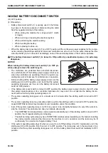
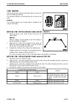


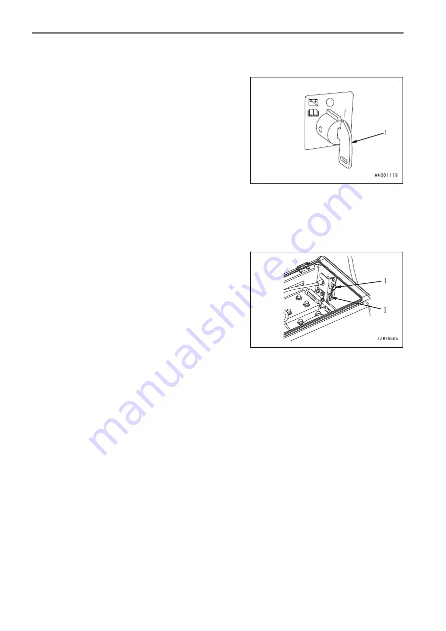
HANDLE BATTERY DISCONNECT SWITCH
(O): OFF position
(I): ON position
• Battery disconnect switch (1) is usually used in the follow-
ing cases in the same purpose of disconnecting the cable
from the negative terminal of the battery.
• When storing the machine for a long period (1 month
or longer)
• When servicing or repairing the electrical system
• When performing the electric welding
• When handling the battery
• When replacing the fuse, etc.
• When the battery disconnect switch (1) is at OFF position, all the continuous power supplies for the compo-
nents including the starting switch B terminal and controllers are all cut out. It is the same state as the time
when the battery is not connected. Accordingly, none of the electrical systems of the machine operates.
k
If the battery disconnect switch (1) is turned to ON position by unauthorized person, it is extremely
dangerous.
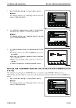
NOTICE
When turning the battery disconnect switch (1) to OFF po-
sition, always remove the switch key (1).
• The controllers are protected from abnormal disconnec-
tion, which shuts off the battery power supply circuit even
when the controllers are operating. Check the system op-
erating lamp (2) is lit and see if controllers are in operation.
• Before shutting off the battery power supply circuit, turn the
starting switch to OFF position, and check that the system
operating lamp goes out, then turn the battery disconnect
switch to OFF position.
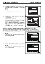
• If the battery disconnect switch is turned to OFF position (the battery power supply circuit is shut off) while
the system operating lamp is lit, a controller data loss error may occur. Do not operate the battery discon-
nect switch while the system operating lamp is lit.
• The system operating lamp goes out in a maximum of 6 minutes after the starting switch is turned to OFF
position.
• The system operating lamp may sometimes light up while the starting switch is turned to OFF position be-
cause KOMTRAX terminal may maintain its communication under this condition.
• Even if the system operating lamp is not lit it may seem to be lit slightly because of a very little current in-
side the controller. This phenomenon does not indicate abnormality.
• The KOMTRAX terminal performs communication periodically even if the starting switch is kept in OFF
position, thus it repeats starting and stopping.
• The start and stop cycle (sleep cycle) of KOMTRAX terminal varies depending on the factors including
the communication state and the time when the machine is not in operation, and the lamp may be lit
continuously for a maximum of approximately 1 hour.
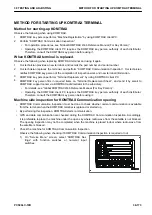
• If the system operating lamp stays lit when you want to cut off the battery circuit for maintenance, turn the
starting switch to ON position first, then turn it to OFF position. The lamp goes out in the maximum of six
minutes. After the system operating lamp goes out, turn the battery disconnect switch immediately to OFF
position.
HANDLE BATTERY DISCONNECT SWITCH
30 TESTING AND ADJUSTING
30-182
PC500LC-10R
Содержание PC500LC-10R
Страница 1: ...HYDRAULIC EXCAVATOR SEN06722 00 PC500LC 10R SERIAL NUMBERS 100001 and up...
Страница 2: ......
Страница 3: ...00 INDEX AND FOREWORD PC500LC 10R 00 1...
Страница 76: ......
Страница 77: ...01 SPECIFICATIONS PC500LC 10R 01 1...
Страница 94: ......
Страница 95: ...10 STRUCTURE AND FUNCTION PC500LC 10R 10 1...
Страница 106: ...8 System operating lamp 9 Fusible link LAYOUT DRAWING OF BOOT UP SYSTEM 10 STRUCTURE AND FUNCTION 10 12 PC500LC 10R...
Страница 177: ...When balanced 10 STRUCTURE AND FUNCTION CLSS PC500LC 10R 10 83...
Страница 178: ...When lever is returned to fine control state CLSS 10 STRUCTURE AND FUNCTION 10 84 PC500LC 10R...
Страница 179: ...When lever is pulled at a stroke 10 STRUCTURE AND FUNCTION CLSS PC500LC 10R 10 85...
Страница 180: ...When lever is in stroke end CLSS 10 STRUCTURE AND FUNCTION 10 86 PC500LC 10R...
Страница 345: ...21 Center swivel joint 22 Travel motor 10 STRUCTURE AND FUNCTION LAYOUT DRAWING OF TRAVEL SYSTEM PC500LC 10R 10 251...
Страница 377: ...20 STANDARD VALUE TABLE PC500LC 10R 20 1...
Страница 406: ...Fig 13 Fig 14 Fig 15 MACHINE POSTURE AND PROCEDURE FOR MEASURING PER FORMANCE 20 STANDARD VALUE TABLE 20 30 PC500LC 10R...
Страница 407: ...30 TESTING AND ADJUSTING PC500LC 10R 30 1...
Страница 423: ...Socket Plug 30 TESTING AND ADJUSTING SKETCH OF TOOLS FOR TESTING AND ADJUSTING PC500LC 10R 30 17...
Страница 583: ...30 TESTING AND ADJUSTING METHOD FOR STARTING UP KOMTRAX TERMINAL PC500LC 10R 30 177...
Страница 604: ......
Страница 605: ...60 MAINTENANCE STANDARD PC500LC 10R 60 1...
Страница 619: ...MAINTENANCE STANDARD OF FINAL DRIVE 60 MAINTENANCE STANDARD MAINTENANCE STANDARD OF FINAL DRIVE PC500LC 10R 60 15...
Страница 623: ...60 MAINTENANCE STANDARD MAINTENANCE STANDARD OF SPROCKET TOOTH PROFILE FULL SCALE DRAWING PC500LC 10R 60 19...
Страница 626: ...MAINTENANCE STANDARD OF IDLER MAINTENANCE STANDARD OF IDLER 60 MAINTENANCE STANDARD 60 22 PC500LC 10R...
Страница 636: ...MAINTENANCE STANDARD OF MAIN PUMP 60 MAINTENANCE STANDARD 60 32 PC500LC 10R...
Страница 637: ...MAINTENANCE STANDARD OF SWING MOTOR 60 MAINTENANCE STANDARD MAINTENANCE STANDARD OF SWING MOTOR PC500LC 10R 60 33...
Страница 638: ...MAINTENANCE STANDARD OF SWING MOTOR 60 MAINTENANCE STANDARD 60 34 PC500LC 10R...
Страница 641: ...60 MAINTENANCE STANDARD MAINTENANCE STANDARD OF TRAVEL MOTOR PC500LC 10R 60 37...
Страница 643: ...MAINTENANCE STANDARD OF CONTROL VALVE 60 MAINTENANCE STANDARD MAINTENANCE STANDARD OF CONTROL VALVE PC500LC 10R 60 39...
Страница 644: ...MAINTENANCE STANDARD OF CONTROL VALVE 60 MAINTENANCE STANDARD 60 40 PC500LC 10R...
Страница 646: ...MAINTENANCE STANDARD OF CONTROL VALVE 60 MAINTENANCE STANDARD 60 42 PC500LC 10R...
Страница 648: ...MAINTENANCE STANDARD OF CONTROL VALVE 60 MAINTENANCE STANDARD 60 44 PC500LC 10R...
Страница 650: ...MAINTENANCE STANDARD OF CONTROL VALVE 60 MAINTENANCE STANDARD 60 46 PC500LC 10R...
Страница 652: ...MAINTENANCE STANDARD OF CONTROL VALVE 60 MAINTENANCE STANDARD 60 48 PC500LC 10R...
Страница 655: ...60 MAINTENANCE STANDARD MAINTENANCE STANDARD OF WORK EQUIPMENT AND SWING PPC VALVE PC500LC 10R 60 51...
Страница 658: ...MAINTENANCE STANDARD OF TRAVEL PPC VALVE 60 MAINTENANCE STANDARD 60 54 PC500LC 10R...
Страница 668: ...MAINTENANCE STANDARD OF WORK EQUIPMENT LINKAGE 60 MAINTENANCE STANDARD 60 64 PC500LC 10R...
Страница 674: ...DIMENSIONS OF BUCKET MAINTENANCE STANDARD OF WORK EQUIPMENT LINKAGE 60 MAINTENANCE STANDARD 60 70 PC500LC 10R...
Страница 679: ...90 CIRCUIT DIAGRAMS PC500LC 10R 90 1...
Страница 690: ...Symbol Content Unit SYMBOLS USED IN HYDRAULIC CIRCUIT DIAGRAM 90 CIRCUIT DIAGRAMS 90 12 PC500LC 10R...
Страница 692: ......
Страница 694: ......
Страница 696: ......
Страница 698: ......
Страница 700: ......
Страница 704: ...Symbol Content Buzzer Antenna SYMBOLS USED IN ELECTRICAL CIRCUIT DIAGRAM 90 26 PC500LC 10R...
Страница 706: ......
Страница 708: ......
Страница 710: ......
Страница 712: ......
Страница 714: ......
Страница 716: ......
Страница 718: ......
Страница 720: ......
Страница 722: ......
Страница 724: ......
Страница 726: ......
Страница 728: ......
Страница 730: ......
Страница 732: ......
Страница 734: ......
Страница 736: ......
Страница 738: ......
Страница 740: ......
Страница 742: ......
Страница 744: ......
Страница 746: ......
Страница 748: ......
Страница 757: ......
Страница 758: ...PC500LC 10R HYDRAULIC EXCAVATOR Form No SEN06722 00 2018 KOMATSU All Rights Reserved Printed in Japan 11 2018...