


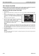

TEST FUEL CIRCUIT FOR LEAKAGE
Tools for testing fuel circuit for leakage
Symbol
Part No.
Part name
Q'ty
Remarks
A
Commercially
available
Developer for dye penetrant (color
checker)
1
k
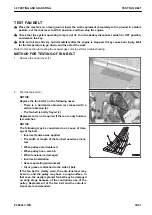
Very high pressure is generated in the high-pressure circuit of the fuel system. If fuel leaks while the
engine is running, it presents a serious danger that could result in a fire. When the fuel circuit is test-
ed or any component is removed from or installed to it, check for fuel leakage according to the fol-
lowing procedure.
k
Place the machine on a level ground, and then lower the work equipment completely to the ground in
a stable posture. Set the lock lever to LOCK position, and then stop the engine.
k
Parts and oil are still very hot immediately after the engine is stopped. It may cause burn injury. Wait
for the temperature to go down, and then start the work.
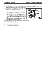
Clean the engine and the parts around it, and degrease them in advance so that you can easily find the leakage
if any.
For testing the fuel system for leakage to perform troubleshooting, refer to this section.
METHOD FOR TESTING FUEL CIRCUIT FOR LEAKAGE
Testing method of fuel circuit for leakage at engine stopped
1.
Start the engine.
2.
Run the engine with fuel control dial at MIN (Low idle), and stop it after the engine automatic warm-up func-
tion is canceled automatically and engine speed is stabilized.
REMARK
• Turn the fuel control dial to MAX (High idle), the engine automatic warm-up function is canceled.
• For the condition of canceling the engine automatic warm-up function, see “ENGINE AUTOMATIC
WARM-UP SYSTEM”.
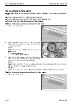
3.
Spray color checker A to the supply pump, common rail, injectors, and joints of the high-pressure piping.
4.
Check the fuel piping and component for fuel leakage.
• Check the high-pressure circuit for fuel leakage focusing on the area where the color checker A is
sprayed.
• If any fuel leakage is detected, repair it and perform the checks from step 1 again.
Testing method of fuel circuit for leakage at engine low idle
1.
Start the engine.
2.
Run the engine with fuel control dial at MIN (Low idle), and stop it after the engine automatic warm-up func-
tion is canceled automatically and engine speed is stabilized.
REMARK
• Turn the fuel control dial to MAX (High idle), the engine automatic warm-up function is canceled.
• For the condition of canceling the engine automatic warm-up function, see “ENGINE AUTOMATIC
WARM-UP SYSTEM”.
3.
Spray color checker A to the supply pump, common rail, injectors, and joints of the high-pressure piping.
4.
Start the engine, and set the fuel control dial to MIN (Low idle).
5.
Stop the engine and check the fuel piping and component for fuel leakage.
• Check the high-pressure circuit for fuel leakage focusing on the area where the color checker A is
sprayed.
• If any fuel leakage is detected, repair it and perform the checks from step 1 again.
30 TESTING AND ADJUSTING
TEST FUEL CIRCUIT FOR LEAKAGE
PC500LC-10R
30-47
Содержание PC500LC-10R
Страница 1: ...HYDRAULIC EXCAVATOR SEN06722 00 PC500LC 10R SERIAL NUMBERS 100001 and up...
Страница 2: ......
Страница 3: ...00 INDEX AND FOREWORD PC500LC 10R 00 1...
Страница 76: ......
Страница 77: ...01 SPECIFICATIONS PC500LC 10R 01 1...
Страница 94: ......
Страница 95: ...10 STRUCTURE AND FUNCTION PC500LC 10R 10 1...
Страница 106: ...8 System operating lamp 9 Fusible link LAYOUT DRAWING OF BOOT UP SYSTEM 10 STRUCTURE AND FUNCTION 10 12 PC500LC 10R...
Страница 177: ...When balanced 10 STRUCTURE AND FUNCTION CLSS PC500LC 10R 10 83...
Страница 178: ...When lever is returned to fine control state CLSS 10 STRUCTURE AND FUNCTION 10 84 PC500LC 10R...
Страница 179: ...When lever is pulled at a stroke 10 STRUCTURE AND FUNCTION CLSS PC500LC 10R 10 85...
Страница 180: ...When lever is in stroke end CLSS 10 STRUCTURE AND FUNCTION 10 86 PC500LC 10R...
Страница 345: ...21 Center swivel joint 22 Travel motor 10 STRUCTURE AND FUNCTION LAYOUT DRAWING OF TRAVEL SYSTEM PC500LC 10R 10 251...
Страница 377: ...20 STANDARD VALUE TABLE PC500LC 10R 20 1...
Страница 406: ...Fig 13 Fig 14 Fig 15 MACHINE POSTURE AND PROCEDURE FOR MEASURING PER FORMANCE 20 STANDARD VALUE TABLE 20 30 PC500LC 10R...
Страница 407: ...30 TESTING AND ADJUSTING PC500LC 10R 30 1...
Страница 423: ...Socket Plug 30 TESTING AND ADJUSTING SKETCH OF TOOLS FOR TESTING AND ADJUSTING PC500LC 10R 30 17...
Страница 583: ...30 TESTING AND ADJUSTING METHOD FOR STARTING UP KOMTRAX TERMINAL PC500LC 10R 30 177...
Страница 604: ......
Страница 605: ...60 MAINTENANCE STANDARD PC500LC 10R 60 1...
Страница 619: ...MAINTENANCE STANDARD OF FINAL DRIVE 60 MAINTENANCE STANDARD MAINTENANCE STANDARD OF FINAL DRIVE PC500LC 10R 60 15...
Страница 623: ...60 MAINTENANCE STANDARD MAINTENANCE STANDARD OF SPROCKET TOOTH PROFILE FULL SCALE DRAWING PC500LC 10R 60 19...
Страница 626: ...MAINTENANCE STANDARD OF IDLER MAINTENANCE STANDARD OF IDLER 60 MAINTENANCE STANDARD 60 22 PC500LC 10R...
Страница 636: ...MAINTENANCE STANDARD OF MAIN PUMP 60 MAINTENANCE STANDARD 60 32 PC500LC 10R...
Страница 637: ...MAINTENANCE STANDARD OF SWING MOTOR 60 MAINTENANCE STANDARD MAINTENANCE STANDARD OF SWING MOTOR PC500LC 10R 60 33...
Страница 638: ...MAINTENANCE STANDARD OF SWING MOTOR 60 MAINTENANCE STANDARD 60 34 PC500LC 10R...
Страница 641: ...60 MAINTENANCE STANDARD MAINTENANCE STANDARD OF TRAVEL MOTOR PC500LC 10R 60 37...
Страница 643: ...MAINTENANCE STANDARD OF CONTROL VALVE 60 MAINTENANCE STANDARD MAINTENANCE STANDARD OF CONTROL VALVE PC500LC 10R 60 39...
Страница 644: ...MAINTENANCE STANDARD OF CONTROL VALVE 60 MAINTENANCE STANDARD 60 40 PC500LC 10R...
Страница 646: ...MAINTENANCE STANDARD OF CONTROL VALVE 60 MAINTENANCE STANDARD 60 42 PC500LC 10R...
Страница 648: ...MAINTENANCE STANDARD OF CONTROL VALVE 60 MAINTENANCE STANDARD 60 44 PC500LC 10R...
Страница 650: ...MAINTENANCE STANDARD OF CONTROL VALVE 60 MAINTENANCE STANDARD 60 46 PC500LC 10R...
Страница 652: ...MAINTENANCE STANDARD OF CONTROL VALVE 60 MAINTENANCE STANDARD 60 48 PC500LC 10R...
Страница 655: ...60 MAINTENANCE STANDARD MAINTENANCE STANDARD OF WORK EQUIPMENT AND SWING PPC VALVE PC500LC 10R 60 51...
Страница 658: ...MAINTENANCE STANDARD OF TRAVEL PPC VALVE 60 MAINTENANCE STANDARD 60 54 PC500LC 10R...
Страница 668: ...MAINTENANCE STANDARD OF WORK EQUIPMENT LINKAGE 60 MAINTENANCE STANDARD 60 64 PC500LC 10R...
Страница 674: ...DIMENSIONS OF BUCKET MAINTENANCE STANDARD OF WORK EQUIPMENT LINKAGE 60 MAINTENANCE STANDARD 60 70 PC500LC 10R...
Страница 679: ...90 CIRCUIT DIAGRAMS PC500LC 10R 90 1...
Страница 690: ...Symbol Content Unit SYMBOLS USED IN HYDRAULIC CIRCUIT DIAGRAM 90 CIRCUIT DIAGRAMS 90 12 PC500LC 10R...
Страница 692: ......
Страница 694: ......
Страница 696: ......
Страница 698: ......
Страница 700: ......
Страница 704: ...Symbol Content Buzzer Antenna SYMBOLS USED IN ELECTRICAL CIRCUIT DIAGRAM 90 26 PC500LC 10R...
Страница 706: ......
Страница 708: ......
Страница 710: ......
Страница 712: ......
Страница 714: ......
Страница 716: ......
Страница 718: ......
Страница 720: ......
Страница 722: ......
Страница 724: ......
Страница 726: ......
Страница 728: ......
Страница 730: ......
Страница 732: ......
Страница 734: ......
Страница 736: ......
Страница 738: ......
Страница 740: ......
Страница 742: ......
Страница 744: ......
Страница 746: ......
Страница 748: ......
Страница 757: ......
Страница 758: ...PC500LC 10R HYDRAULIC EXCAVATOR Form No SEN06722 00 2018 KOMATSU All Rights Reserved Printed in Japan 11 2018...