


• Be sure to assemble all parts again in their original places. Replace any damaged parts and parts which
must not be reused with new parts. When installing hoses and wiring harnesses, be sure that they will not
be damaged by contact with other parts when the machine is operated.
• When installing high pressure hoses and tubes, make sure that they are not twisted. Damaged hoses and
tubes are dangerous, so be extremely careful when installing hoses and tubes for high pressure circuits. In
addition, check that high pressure hoses and tubes are correctly installed.
• When assembling or installing parts, always tighten them to the specified torques. When installing protec-
tive parts such as guards, or parts which vibrate violently or rotate at high speed, check again that they are
installed correctly.
• Never insert your fingers or hand when aligning 2 holes. Be careful not to get your fingers caught in a hole.
• Check that the measuring tools are correctly installed when measuring hydraulic pressure.
• Take care when removing or installing the tracks of track-type machines. Since the track shoe may sepa-
rate suddenly when you remove it, never let anyone stand at either end of the track shoe.
• If the engine is operated for a long time in a closed place
with poor ventilation, it may cause gas poisoning. Open
the windows and doors to ventilate the place well.
Precautions for slinging work and making signals
• Only one appointed worker must make signals and co-workers must communicate with each other fre-
quently. The appointed signaler must make specified signals clearly at a place where he is well seen from
the operator's seat and where he can see the working condition easily. The signaler must always stand in
front of the load and guide the operator safely.
k
Never stand under the load.
k
Do not move a load over a person.
k
Never step on the load.
k
Do not prevent the load from swinging or falling down by holding it simply with the hands.
k
The sling workers and assistant workers other than the guide must move to a place where they
are not caught between the load and materials or equipment on the ground or hit by the load
even if the crane starts abruptly.
• Check the slings before starting sling work.
• Keep putting on gloves during sling work. (Put on leather gloves, if available.)
• Measure the weight of the load by the eye and check its center of gravity.
• Use proper sling corresponding to the weight of the load and method of slinging. If too thick wire ropes are
used to sling a light load, the load may slip and fall.
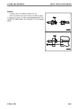
• Do not sling a load with 1 wire rope alone. If it is slung so, it may rotate and may slip out of the rope. Install
2 or more wire ropes symmetrically.
k
Slinging with one rope may cause turning of the load during hoisting, untwisting of the rope, or
slipping of the rope from its original slinging position on the load, which can result in a danger-
ous accident.
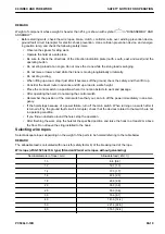
• Hanging angle must be 60 ° or smaller as a rule.
• When slinging a heavy load (25 kg or heavier), the hanging angle of the rope must be narrower than that of
the hook.
,&
00 INDEX AND FOREWORD
SAFETY NOTICE FOR OPERATION
PC500LC-10R
00-17
Содержание PC500LC-10R
Страница 1: ...HYDRAULIC EXCAVATOR SEN06722 00 PC500LC 10R SERIAL NUMBERS 100001 and up...
Страница 2: ......
Страница 3: ...00 INDEX AND FOREWORD PC500LC 10R 00 1...
Страница 76: ......
Страница 77: ...01 SPECIFICATIONS PC500LC 10R 01 1...
Страница 94: ......
Страница 95: ...10 STRUCTURE AND FUNCTION PC500LC 10R 10 1...
Страница 106: ...8 System operating lamp 9 Fusible link LAYOUT DRAWING OF BOOT UP SYSTEM 10 STRUCTURE AND FUNCTION 10 12 PC500LC 10R...
Страница 177: ...When balanced 10 STRUCTURE AND FUNCTION CLSS PC500LC 10R 10 83...
Страница 178: ...When lever is returned to fine control state CLSS 10 STRUCTURE AND FUNCTION 10 84 PC500LC 10R...
Страница 179: ...When lever is pulled at a stroke 10 STRUCTURE AND FUNCTION CLSS PC500LC 10R 10 85...
Страница 180: ...When lever is in stroke end CLSS 10 STRUCTURE AND FUNCTION 10 86 PC500LC 10R...
Страница 345: ...21 Center swivel joint 22 Travel motor 10 STRUCTURE AND FUNCTION LAYOUT DRAWING OF TRAVEL SYSTEM PC500LC 10R 10 251...
Страница 377: ...20 STANDARD VALUE TABLE PC500LC 10R 20 1...
Страница 406: ...Fig 13 Fig 14 Fig 15 MACHINE POSTURE AND PROCEDURE FOR MEASURING PER FORMANCE 20 STANDARD VALUE TABLE 20 30 PC500LC 10R...
Страница 407: ...30 TESTING AND ADJUSTING PC500LC 10R 30 1...
Страница 423: ...Socket Plug 30 TESTING AND ADJUSTING SKETCH OF TOOLS FOR TESTING AND ADJUSTING PC500LC 10R 30 17...
Страница 583: ...30 TESTING AND ADJUSTING METHOD FOR STARTING UP KOMTRAX TERMINAL PC500LC 10R 30 177...
Страница 604: ......
Страница 605: ...60 MAINTENANCE STANDARD PC500LC 10R 60 1...
Страница 619: ...MAINTENANCE STANDARD OF FINAL DRIVE 60 MAINTENANCE STANDARD MAINTENANCE STANDARD OF FINAL DRIVE PC500LC 10R 60 15...
Страница 623: ...60 MAINTENANCE STANDARD MAINTENANCE STANDARD OF SPROCKET TOOTH PROFILE FULL SCALE DRAWING PC500LC 10R 60 19...
Страница 626: ...MAINTENANCE STANDARD OF IDLER MAINTENANCE STANDARD OF IDLER 60 MAINTENANCE STANDARD 60 22 PC500LC 10R...
Страница 636: ...MAINTENANCE STANDARD OF MAIN PUMP 60 MAINTENANCE STANDARD 60 32 PC500LC 10R...
Страница 637: ...MAINTENANCE STANDARD OF SWING MOTOR 60 MAINTENANCE STANDARD MAINTENANCE STANDARD OF SWING MOTOR PC500LC 10R 60 33...
Страница 638: ...MAINTENANCE STANDARD OF SWING MOTOR 60 MAINTENANCE STANDARD 60 34 PC500LC 10R...
Страница 641: ...60 MAINTENANCE STANDARD MAINTENANCE STANDARD OF TRAVEL MOTOR PC500LC 10R 60 37...
Страница 643: ...MAINTENANCE STANDARD OF CONTROL VALVE 60 MAINTENANCE STANDARD MAINTENANCE STANDARD OF CONTROL VALVE PC500LC 10R 60 39...
Страница 644: ...MAINTENANCE STANDARD OF CONTROL VALVE 60 MAINTENANCE STANDARD 60 40 PC500LC 10R...
Страница 646: ...MAINTENANCE STANDARD OF CONTROL VALVE 60 MAINTENANCE STANDARD 60 42 PC500LC 10R...
Страница 648: ...MAINTENANCE STANDARD OF CONTROL VALVE 60 MAINTENANCE STANDARD 60 44 PC500LC 10R...
Страница 650: ...MAINTENANCE STANDARD OF CONTROL VALVE 60 MAINTENANCE STANDARD 60 46 PC500LC 10R...
Страница 652: ...MAINTENANCE STANDARD OF CONTROL VALVE 60 MAINTENANCE STANDARD 60 48 PC500LC 10R...
Страница 655: ...60 MAINTENANCE STANDARD MAINTENANCE STANDARD OF WORK EQUIPMENT AND SWING PPC VALVE PC500LC 10R 60 51...
Страница 658: ...MAINTENANCE STANDARD OF TRAVEL PPC VALVE 60 MAINTENANCE STANDARD 60 54 PC500LC 10R...
Страница 668: ...MAINTENANCE STANDARD OF WORK EQUIPMENT LINKAGE 60 MAINTENANCE STANDARD 60 64 PC500LC 10R...
Страница 674: ...DIMENSIONS OF BUCKET MAINTENANCE STANDARD OF WORK EQUIPMENT LINKAGE 60 MAINTENANCE STANDARD 60 70 PC500LC 10R...
Страница 679: ...90 CIRCUIT DIAGRAMS PC500LC 10R 90 1...
Страница 690: ...Symbol Content Unit SYMBOLS USED IN HYDRAULIC CIRCUIT DIAGRAM 90 CIRCUIT DIAGRAMS 90 12 PC500LC 10R...
Страница 692: ......
Страница 694: ......
Страница 696: ......
Страница 698: ......
Страница 700: ......
Страница 704: ...Symbol Content Buzzer Antenna SYMBOLS USED IN ELECTRICAL CIRCUIT DIAGRAM 90 26 PC500LC 10R...
Страница 706: ......
Страница 708: ......
Страница 710: ......
Страница 712: ......
Страница 714: ......
Страница 716: ......
Страница 718: ......
Страница 720: ......
Страница 722: ......
Страница 724: ......
Страница 726: ......
Страница 728: ......
Страница 730: ......
Страница 732: ......
Страница 734: ......
Страница 736: ......
Страница 738: ......
Страница 740: ......
Страница 742: ......
Страница 744: ......
Страница 746: ......
Страница 748: ......
Страница 757: ......
Страница 758: ...PC500LC 10R HYDRAULIC EXCAVATOR Form No SEN06722 00 2018 KOMATSU All Rights Reserved Printed in Japan 11 2018...