TP-6126 8/02
20
Section 3 Setup and Test
3.3.1
Main Logic Board DIP Switch
Settings
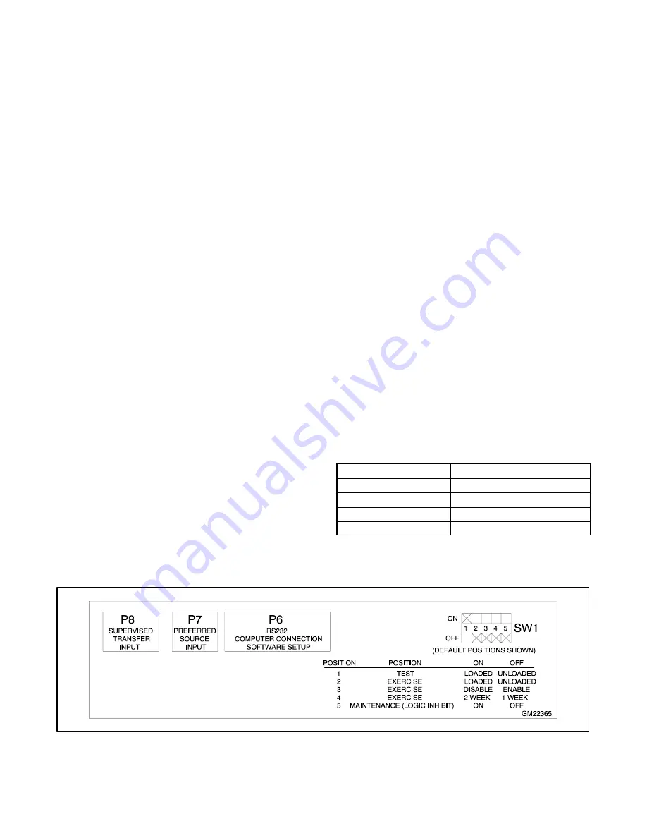
DIP switches on the main logic board control the test and
exercise functions. A maintenance DIP switch inhibits
transfer during ATS service. The factory settings for the
DIP switches are shown in Figure 3-8.
Before opening the transfer switch enclosure to check or
change the DIP switch settings, open the circuit
breakers to disconnect the power to the transfer switch.
The DIP switches are located on the controller’s main
logic board on the inside of the enclosure door.
Figure 3-6 shows the locations of the switches on the
controller circuit board. A decal on the logic assembly
housing shows the DIP switch positions and settings
(see Figure 3-8). It is not necessary to remove the logic
assembly cover to see or adjust the DIP switches.
Check the DIP switch settings and adjust if necessary
for the application.
Note:
Changing the position of the 1 week/2 week
exercise DIP switch after the exerciser has been
set does not change the time of the
next
scheduled exercise. The new DIP switch setting
becomes effective
after
the next scheduled
exercise. See Section 4.2.3 for more information
about the exerciser.
Close and lock the enclosure door before energizing the
transfer switch.
3.3.2
Main Logic Board Inputs and
Outputs
The controller main logic board’s inputs and outputs are
factory-assigned to the functions shown in Figure 3-7.
Pre-Transfer Load Control Output.
Assigned to
terminals TB1-1 and TB1-2. The load control output
operates only during the transfer sequence between
two live sources. When the output is activated, the
contact opens for the programmed length of time before
transfer (default setting=3 seconds) to allow controlled
disconnection of selected loads. The contact closes at
the time of transfer (default post-transfer time delay
setting=0). The contact is not activated if the controller
detects no available source.
See Section 4.2.5 for more information about the
pre-transfer and post-transfer load control signal
operation sequence. The pre- and post-transfer time
delays can be adjusted using the optional setup
program.
Load Bank Control Output.
Assigned to terminals
TB1-3--TB1-5 (programmable). The load bank control
output can be used to apply a load to the generator set
during the exercise. The load bank control output closes
or opens a contact that can be used to signal the load
bank controller to operate. If the Normal source is lost
during an exercise period, the load bank control output
is deactivated to remove the load bank and allow the
transfer of the building load to the emergency source.
Peak Shave/Area Protection Input.
Assigned to
terminals TB1-6 and TB1-7 (programmable input #1).
Starts the generator set and transfers to the standby
source, ignoring the Time Delay Engine Start and
Standby-to-Preferred
time
delays.
The
system
attempts to transfer to the preferred source when the
input is removed.
The peak shave command is
overridden if the standby source fails.
TB1 Input/Output
Factory Setting
Non-programmable output
Pre-transfer load control
Programmable output
Load bank control output
Programmable input #1
Peak shave/Area protection input
Programmable input #2
End time delay input
Figure 3-7
Terminal Strip Input and Output Factory
Settings
Figure 3-8
Logic Assembly Decal Showing DIP Switch Settings
Содержание KCP MPAC 1000
Страница 22: ...TP 6126 8 02 12 Section 2 Installation ADV 6736 Figure 2 20 Interconnection Diagram...
Страница 75: ......


