


TP-6069 6/03
72
Section 8 Reconnection/Adjustments
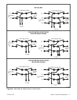
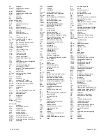
7
6
8
5
11
10
12
9
15
14
16
13
L2
L3
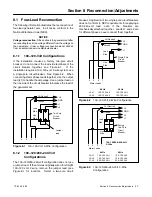
To Generator
Set
To Shore
Power
To Load
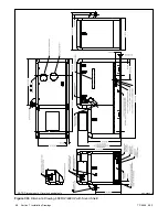
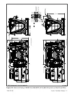
4-Wire, 3-Phase Generator Sets
L0
3
2
4
1
L1
L2
L3
L0
L1
L2
L3
L0
L1
Kraus Naimler/American Solenoid
I-940
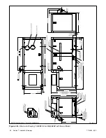
Figure 8-10
Marine Manual (Ship-to-Shore) Transfer
Switch, continued
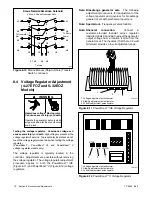
8.4 Voltage Regulator Adjustment
(4--27EFOZ and 5--32EOZ
Models)
Hazardous voltage.
Can cause severe injury or death.
Operate the generator set only when
all guards and electrical enclosures
are in place.
Moving rotor.
WARNING
Testing the voltage regulator. Hazardous voltage can
cause severe injury or death.
High voltage is present at the
voltage regulator heat sink. To prevent electrical shock do not
touch the voltage regulator heat sink when testing the voltage
regulator.
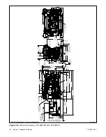
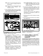
(PowerBoost
t
,
PowerBoost
t
III,
and
PowerBoost
t
V
voltage regulator models only)
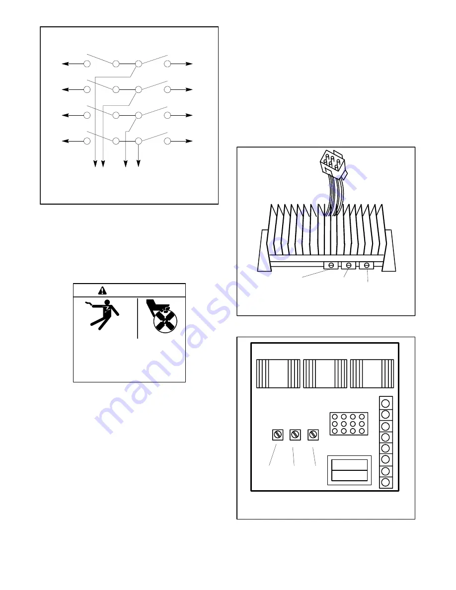
The voltage regulator is typically located in the
controller. Adjustments are possible without removing
the voltage regulator. The voltage regulator adjustment
procedure applies to both the PowerBoost
IIIE
(Figure 8-11) and PowerBoost
V (Figure 8-12) voltage
regulators.
Note: Broadrange generator sets.
The following
adjustment procedure is for readjustment of the
voltage regulator and governor for broadrange
generator sets with mechanical governors.
Note: Special tool.
Frequency meter 50/60 Hz.
Note: Rheostat
connection.
Connect
a
customer-provided rheostat across regulator
leads/terminals 33 and 66 to adjust the generator
output voltage from a location remote from the
generator set. The rheostat (10 kOhms, 1/2 watt
minimum) provides a 5-volt adjustment range.
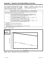
TT-875-11
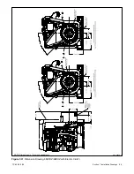
1
2
3
1. Voltage adjustment potentiometer
2. Stability adjustment potentiometer
3. Volts/Hz adjustment potentiometer
Figure 8-11
PowerBoost
IIIE Voltage Regulator
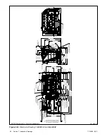
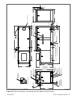
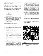
8
7
6
5
4
3
2
1
VOLTS
V/HZ
STAB
TT-875-11
2
3
1
1. Voltage adjustment potentiometer
2. Stability adjustment potentiometer
3. Volts/Hz adjustment potentiometer
Figure 8-12
PowerBoost
V Voltage Regulator
Содержание 100EFOZ
Страница 2: ......
Страница 4: ......
Страница 10: ...TP 6069 6 03 VI Safety Precautions and Instructions Notes ...
Страница 12: ...TP 6069 6 03 2 Section 1 Introduction Notes ...
Страница 14: ...TP 6069 6 03 4 Section 2 Location and Mounting Notes ...
Страница 20: ...TP 6069 6 03 10 Section 3 Cooling System Notes ...
Страница 26: ...TP 6069 6 03 16 Section 4 Exhaust System Notes ...
Страница 37: ...TP 6069 6 03 27 Section 6 Electrical System Figure 6 10 Remote Controller and Harness Options 33 150 kW Models ...
Страница 38: ...TP 6069 6 03 28 Section 6 Electrical System Notes ...
Страница 41: ...TP 6069 6 03 31 Section 7 Installation Drawings ADV 6652B B Figure 7 3 Remote Options 3 5EFOZ 4EOZ ...
Страница 84: ...TP 6069 6 03 74 Section 8 Reconnection Adjustments Notes ...
Страница 89: ......
Страница 90: ......
Страница 91: ......