


TP-6069 6/03
68
Section 8 Reconnection/Adjustments
8.1.3
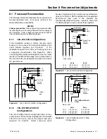
200--240-Volt Configurations
The 200--240-volt configuration does not use a jumper
lead. If the unit was originally wired for straight 100--120
volt, 3-wire, remove the jumper lead (see Figure 8-1 for
location).
4
3
2
1
Stator Leads
L0
GRD.
L1
L0 (Neutral)
Line
Side
Single-Pole
Circuit
Breaker
Ground
Load
Side
200--220--240 Volt
2 Wire
Tape to insulate
from ground
60 Hz
L0--L1
200-240 Volt 200--220--240 Volt
50 Hz
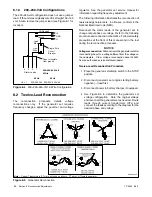
Figure 8-4
200--220--240-Volt, 2-Wire Configuration
8.2 Twelve-Lead Reconnection
The
reconnection
procedure
details
voltage
reconnections only.
If the generator set requires
frequency changes, adjust the governor and voltage
regulator. See the generator set service manual for
information regarding frequency adjustment.
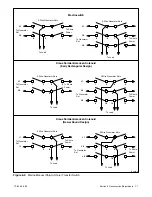
The following information illustrates the reconnection of
twelve-lead generator sets. In all cases, conform to the
National Electrical Code (NEC).
Reconnect the stator leads of the generator set to
change output phase or voltage. Refer to the following
procedure and connection schematics. Follow all safety
precautions at the front of this manual and in the text
during the reconnection procedure.
NOTICE
Voltage reconnection.
Affix a notice to the generator set after
reconnecting the set to a voltage different from the voltage on
the nameplate. Order voltage reconnection decal 246242
from an authorized service distributor/dealer.
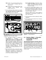
Twelve-Lead Reconnection Procedure
1. Place the generator start/stop switch in the STOP
position.
2. Disconnect generator set engine starting battery,
negative (--) lead first.
3. Disconnect power to battery charger, if equipped.
4. Use Figure 8-5 to determine the generator set
voltage configuration.
Note the original voltage
and reconnect the generator set as needed. Route
leads through current transformers (CTs) and
connect the leads according to the diagram for the
desired phase and voltage.
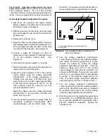
EM-250000-E
Note:
Current Transformers (CTs) are not used on all sets. CT dot or “HI” toward generator.
Figure 8-5
Generator Reconnection
Содержание 100EFOZ
Страница 2: ......
Страница 4: ......
Страница 10: ...TP 6069 6 03 VI Safety Precautions and Instructions Notes ...
Страница 12: ...TP 6069 6 03 2 Section 1 Introduction Notes ...
Страница 14: ...TP 6069 6 03 4 Section 2 Location and Mounting Notes ...
Страница 20: ...TP 6069 6 03 10 Section 3 Cooling System Notes ...
Страница 26: ...TP 6069 6 03 16 Section 4 Exhaust System Notes ...
Страница 37: ...TP 6069 6 03 27 Section 6 Electrical System Figure 6 10 Remote Controller and Harness Options 33 150 kW Models ...
Страница 38: ...TP 6069 6 03 28 Section 6 Electrical System Notes ...
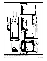
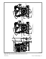
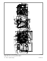
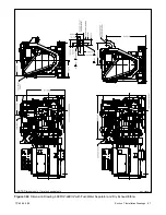
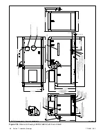
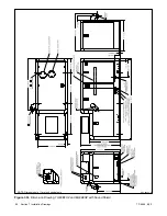
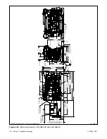
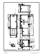
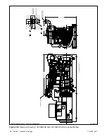
Страница 41: ...TP 6069 6 03 31 Section 7 Installation Drawings ADV 6652B B Figure 7 3 Remote Options 3 5EFOZ 4EOZ ...
Страница 84: ...TP 6069 6 03 74 Section 8 Reconnection Adjustments Notes ...
Страница 89: ......
Страница 90: ......
Страница 91: ......


