


TP-6069 6/03
67
Section 8 Reconnection/Adjustments
Section 8 Reconnection/Adjustments
8.1 Four-Lead Reconnection
The following information illustrates the reconnection of
four-lead generator sets. In all cases, conform to the
National Electrical Code (NEC).
NOTICE
Voltage reconnection.
Affix a notice to the generator set after
reconnecting the set to a voltage different from the voltage on
the nameplate. Order voltage reconnection decal 246242
from an authorized service distributor/dealer.
8.1.1
100--120-Volt Configurations
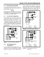
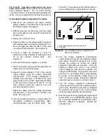
If the installation requires a factory two-pole circuit
breaker, do not connect the load-side terminals of the
circuit breaker together; see Figure 8-1.
If the
installation requires a 100--120-volt, 2-wire system, use
a single-pole circuit breaker. See Figure 8-2. When
connecting stator phase leads together, size the output
lead (L1) to handle the amperage. Use a jumper lead on
the
line
side of the circuit breaker to balance the load of
the generator set.
GRD.
L1
L2
4
3
2
1
L0 (Neutral)
L0
Ground
Load
Side
Line
Side
Two-Pole
Circuit
Breaker
Jumper
lead
Figure 8-1
100--120-Volt, 3-Wire Configuration
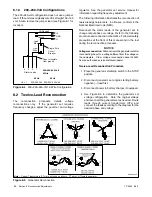
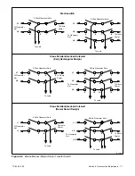
8.1.2
100--120/200--240-Volt
Configurations
The 100--120/200--240-volt configuration does not use
a jumper lead. If the unit was originally wired for straight
100--120 volt, 3-wire, remove the jumper lead (see
Figure 8-1 for location).
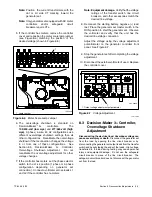
Select a two-pole circuit
breaker. Application of two single-pole circuit breakers
does not conform to NEC requirements for supplying a
200--240-volt
load,
even
if
the
breakers
are
mechanically attached together. Leads L1 and L2 are
for different phases;
never
connect them together.
4
3
2
1
Stator Leads
L0
GRD.
L1
L0 (Neutral)
Line
Side
Single-Pole
Circuit
Breaker
Ground
Load
Side
60 Hz
50 Hz
L0--L1
100--120 Volt
100--120 Volt
L0--L2
100--120 Volt
100--120 Volt
Figure 8-2
100--120-Volt, 2-Wire Configuration
4
3
2
1
Stator Leads
L0
GRD.
L2
L1
L0 (Neutral)
Line
Side
Factory
Two-Pole
Circuit
Breaker
Ground
Load
Side
100--120/200--240-Volt,
3-Wire
60 Hz
50 Hz
L0--L1
100--120 Volt
100--120 Volt
L0--L2
100--120 Volt
100--120 Volt
L1--L2
200--240 Volt
200--240 Volt
Figure 8-3
100--120/200--240-Volt, 3-Wire
Configuration
Содержание 100EFOZ
Страница 2: ......
Страница 4: ......
Страница 10: ...TP 6069 6 03 VI Safety Precautions and Instructions Notes ...
Страница 12: ...TP 6069 6 03 2 Section 1 Introduction Notes ...
Страница 14: ...TP 6069 6 03 4 Section 2 Location and Mounting Notes ...
Страница 20: ...TP 6069 6 03 10 Section 3 Cooling System Notes ...
Страница 26: ...TP 6069 6 03 16 Section 4 Exhaust System Notes ...
Страница 37: ...TP 6069 6 03 27 Section 6 Electrical System Figure 6 10 Remote Controller and Harness Options 33 150 kW Models ...
Страница 38: ...TP 6069 6 03 28 Section 6 Electrical System Notes ...
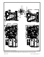
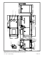
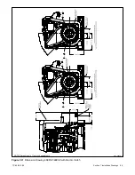
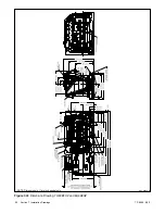
Страница 41: ...TP 6069 6 03 31 Section 7 Installation Drawings ADV 6652B B Figure 7 3 Remote Options 3 5EFOZ 4EOZ ...
Страница 84: ...TP 6069 6 03 74 Section 8 Reconnection Adjustments Notes ...
Страница 89: ......
Страница 90: ......
Страница 91: ......


