


TP-6069 6/03
13
Section 4 Exhaust System
Waterline
1
2
4
5
6
7
8
9
10
11
12
13
14
15
16
3
TP-5856-4
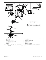
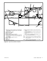
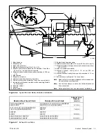
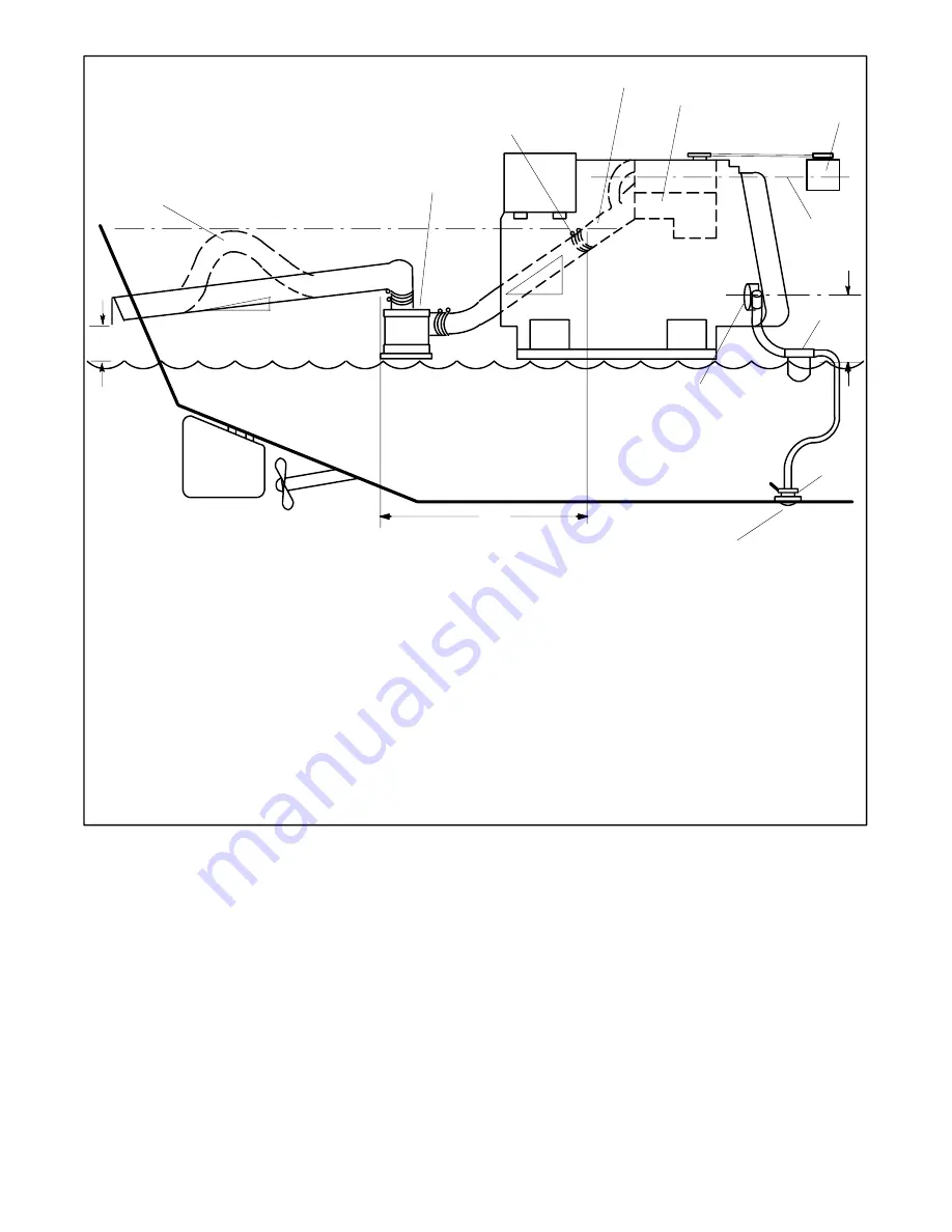
1. Slight lift improves silencing and prevents water backwash
into the silencer (keep below the level of the exhaust
manifold outlet)
2. Silencer (customer-supplied)
3. Exhaust manifold outlet
4. Exhaust mixer elbow
5. Heat exchanger (locations vary by model)
6. Coolant recovery tank (located on the unit on some models)
7. Locate the coolant recovery tank at the same height as the
heat exchanger
8. Maximum seawater pump lift of 1 m (3 ft.)
9. Seawater strainer
10. Seacock
11. Intake strainer
12. Engine-driven seawater pump
13. Minimum exhaust hose pitch of 1.3 cm per 30.5 cm (0.5 in.
per ft.)
14. Maximum distance between silencer and exhaust mixer
elbow of 3 m (10 ft.)
15. Minimum exhaust hose pitch of 1.3 cm per 30.5 cm (0.5 in.
per ft.)
16. Minimum exhaust outlet distance above waterline of 10 cm
(4 in.). Note: Vessel fully loaded.
Note:
Data applies to both rear- and side-exhaust installations.
Note:
Use two hose clamps on each end of all flexible exhaust
hose connections.
Note:
Read the text for complete explanation of dimensions
and other installation considerations.
Figure 4-4
Typical Above-Waterline Installation
Содержание 100EFOZ
Страница 2: ......
Страница 4: ......
Страница 10: ...TP 6069 6 03 VI Safety Precautions and Instructions Notes ...
Страница 12: ...TP 6069 6 03 2 Section 1 Introduction Notes ...
Страница 14: ...TP 6069 6 03 4 Section 2 Location and Mounting Notes ...
Страница 20: ...TP 6069 6 03 10 Section 3 Cooling System Notes ...
Страница 26: ...TP 6069 6 03 16 Section 4 Exhaust System Notes ...
Страница 37: ...TP 6069 6 03 27 Section 6 Electrical System Figure 6 10 Remote Controller and Harness Options 33 150 kW Models ...
Страница 38: ...TP 6069 6 03 28 Section 6 Electrical System Notes ...
Страница 41: ...TP 6069 6 03 31 Section 7 Installation Drawings ADV 6652B B Figure 7 3 Remote Options 3 5EFOZ 4EOZ ...
Страница 84: ...TP 6069 6 03 74 Section 8 Reconnection Adjustments Notes ...
Страница 89: ......
Страница 90: ......
Страница 91: ......


