


TP-6069 6/03
18
Section 5 Fuel System
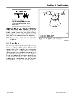
5.2 Fuel Lines
Locate the fuel return line as far as practical from the fuel
pickup to allow the tank fuel to cool the return fuel before
delivery back to the fuel injectors. Incoming fuel cools
the injectors to achieve maximum engine efficiency.
Note:
Do not tee into the main propulsion engine’s fuel
line.
Under no circumstances should the propulsion engine
and generator set share pickup or return lines (through a
tee arrangement) that would allow the larger engine to
starve fuel from the smaller engine. It is possible that the
operation of either engine could completely drain the
fuel line of the other engine and make starting difficult.
Use a flexible hose section to connect the metallic line
from the fuel tank to the engine’s fuel pump inlet
connection point. Also, use a flexible hose section to
connect the metallic line from the fuel tank to the fuel
return connection point. The flexible section allows the
generator set to vibrate during operation.
Model
Fuel Line
ID Size
mm (in.)
3.5EFOZ and 4EOZ
6.4 (1/4)
4--125EFOZ and 5--150EOZ
9.7 (3/8)
Figure 5-2
Fuel Line ID Size
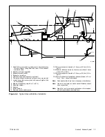
See Figure 5-2 for the ID size of the customer-supplied
fuel line that connects to the fuel pump and fuel return.
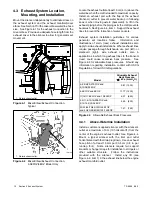
Route the fuel lines from the fuel tank in a gradual incline
to the engine—do not exceed the height of the generator
set and do not route fuel lines above the generator set.
Comply
with
USCG
Regulation
46CFR182.20
regarding fuel lines and supports.
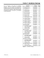
See Section 7 for fuel feed pump inlet connection and
fuel return line connection.
5.3 Fuel Filters
Conform to USCG Regulations regarding inline fuel
filters or strainers.
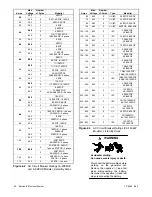
5.4 Fuel Pump Lift
See Figure 5-3 for fuel pump lift capabilities.
Model
Fuel
Pump
Lift
m (ft.)
3.5/4/6.5/8.5/9/11/11.5/13/16/17.5/19/20/23/
27EFOZ and
4/5/8/10/13/14/15.5/20/23/24/28/32EOZ
1.2 (4)
33/40/55/70/80/100/125EFOZ
and 40/50/65/80/99/125/150EOZ
0.9 (3)
Figure 5-3
Fuel Pump Lift
5.5 Fuel Consumption
Consult the current generator set specification sheets
for generator set fuel consumption rates.
Содержание 100EFOZ
Страница 2: ......
Страница 4: ......
Страница 10: ...TP 6069 6 03 VI Safety Precautions and Instructions Notes ...
Страница 12: ...TP 6069 6 03 2 Section 1 Introduction Notes ...
Страница 14: ...TP 6069 6 03 4 Section 2 Location and Mounting Notes ...
Страница 20: ...TP 6069 6 03 10 Section 3 Cooling System Notes ...
Страница 26: ...TP 6069 6 03 16 Section 4 Exhaust System Notes ...
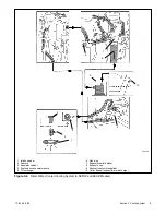
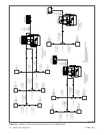
Страница 37: ...TP 6069 6 03 27 Section 6 Electrical System Figure 6 10 Remote Controller and Harness Options 33 150 kW Models ...
Страница 38: ...TP 6069 6 03 28 Section 6 Electrical System Notes ...
Страница 41: ...TP 6069 6 03 31 Section 7 Installation Drawings ADV 6652B B Figure 7 3 Remote Options 3 5EFOZ 4EOZ ...
Страница 84: ...TP 6069 6 03 74 Section 8 Reconnection Adjustments Notes ...
Страница 89: ......
Страница 90: ......
Страница 91: ......


