


TP-6069 6/03
23
Section 6 Electrical System
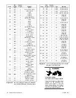
1
2
3
4
5
6
9
1
5
6
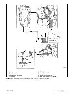
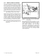
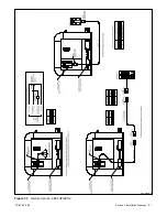
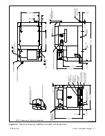
ASSEMBLY VIEW A
ASSEMBLY VIEW B
DX-250000-B
7
8
ASSEMBLY VIEW C-C
1. Existing mounting hardware
2. Load lead access panel
3. Screw
4. Hang tag
5. Circuit breaker
6. Circuit breaker panel
7. Extension leads, if equipped
8. Rear connection used on 125-250 amp circuit breaker
9. Spacer used on 125-250 amp circuit breaker
Figure 6-4
Circuit Breaker Mounting
6.3 Installation In Steel or
Aluminum Vessels
Installation of a generator set in a vessel constructed of
a material capable of conducting current (e.g., steel or
aluminum) is subject to considerations not normally
encountered in fiberglass or wood vessels.
These
differences include equipment grounding, grounding of
neutral
conductors,
ground-fault
protection,
and
isolation of galvanic currents.
The scope of these topics is too extensive to be fully
discussed here. Consult your local marine authority for
more information.
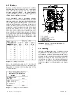
Before installing the generator set, check the available
wiring diagrams in the operation manual to become
familiar with the electrical system.
6.4 Installation Regulations
The
U.S.
Coast
Guard
governs
generator
set
installation in U.S. pleasurecraft and commercial
vessels. Refer to the applicable regulations below:
U.S. Pleasurecraft Installation
Regulations
Title 33CFR, Chapter I, U.S. Coast Guard, Part 183
1. Subpart I—Electrical Equipment
2. Subpart J—Fuel Systems
U.S. Commercial Vessel Installation
Regulations
Title 46CFR, Chapter I, U.S. Coast Guard
1. Part 111—Electrical Systems
2. Part 182—Machinery Installation
m:sc:001:001
Содержание 100EFOZ
Страница 2: ......
Страница 4: ......
Страница 10: ...TP 6069 6 03 VI Safety Precautions and Instructions Notes ...
Страница 12: ...TP 6069 6 03 2 Section 1 Introduction Notes ...
Страница 14: ...TP 6069 6 03 4 Section 2 Location and Mounting Notes ...
Страница 20: ...TP 6069 6 03 10 Section 3 Cooling System Notes ...
Страница 26: ...TP 6069 6 03 16 Section 4 Exhaust System Notes ...
Страница 37: ...TP 6069 6 03 27 Section 6 Electrical System Figure 6 10 Remote Controller and Harness Options 33 150 kW Models ...
Страница 38: ...TP 6069 6 03 28 Section 6 Electrical System Notes ...
Страница 41: ...TP 6069 6 03 31 Section 7 Installation Drawings ADV 6652B B Figure 7 3 Remote Options 3 5EFOZ 4EOZ ...
Страница 84: ...TP 6069 6 03 74 Section 8 Reconnection Adjustments Notes ...
Страница 89: ......
Страница 90: ......
Страница 91: ......


