33/KODAK M-SERIES PROJECTORS
completely out of the film aperture at the slowest run-
ning speed, the snap ring is too far in. Move the snap
ring closer to the lower end of the still-mask changeover
rod—the direction of arrow #1, Fig. D112.
-if the still-frame heat-absorbing filter doesn't move
completely into the film aperture at the still setting, the
snap ring is too far out. Increase the distance between
the snap ring and the lower end of the still-mask
changeover rod—move the snap ring in the direction of
arrow #2, Fig. D112.
2. Forward/reverse arm.
As you change between forward
and reverse, the forward/reverse arm shifts the position of
the shutter-drive shaft. The forward/reverse arm pushes the
shutter-drive shaft slightly closer to the shutter at the reverse
setting. At the forward setting, the forward-reverse arm
allows the shutter-drive shaft to move slightly away from the
shutter.
The in/out position of the shutter-drive shaft determines
which of two lugs on the shutter will be engaged by the drive
dog at the end of the shutter-drive shaft. In Fig. D113 and
Fig. D114, we've assembled a shutter to the shutter-drive
shaft to illustrate the operation.
On reverse, you've seen that the forward/reverse arm pushes
the shutter-drive shaft toward the shutter. The dog at the end
of the shutter-drive shaft then picks up the inner lug at the
back of the shutter, Fig. D113. On forward, the spring-driven
shutter-drive shaft moves slightly away from the shutter. The
dog at the end of the shutter-drive shaft then picks up the
outer lug at the back of the shutter, Fig. D114.
Watch the shutter-drive shaft as you shift the projector
between forward and reverse—make sure the dog on the
shutter-drive shaft engages the proper lug on the shutter. If
the shutter-drive shaft won't move back far enough to engage
the outer lug on the shutter, adjust the eccentric on the
forward/reverse arm, Fig. D116. Similarly, adjust the
eccentric if the shutter-drive shaft won't move in far enough
to engage the inner lug on the shutter. But first make sure
that the shutter-drive shaft is free to move in. If one of the
springs at the back of the shutter is bent, it may be blocking
the shutter-drive shaft, Fig. D115.
3. Testing film advance.
For safety, always install the
bottom cover before plugging in the projector. If you've just
repaired the projector, it's not as necessary as yet to replace
the bottom-cover screws—just make sure the bottom cover is
in place.
Next install the lamp and the film-path cover plate. Also
replace the pressure plate, Fig. D117, and the lens; it's not
necessary to replace the front cover for tests and adjust-
ments. You can now check the projector with test film. If
you're repairing the projector for someone else,
always use
test film
—don't risk damage to the customer's film.
When you're checking with super 8 film, install the super-8
adapter over the supply spindle. Remove the super-8 adapter
to check with regular-8 film.
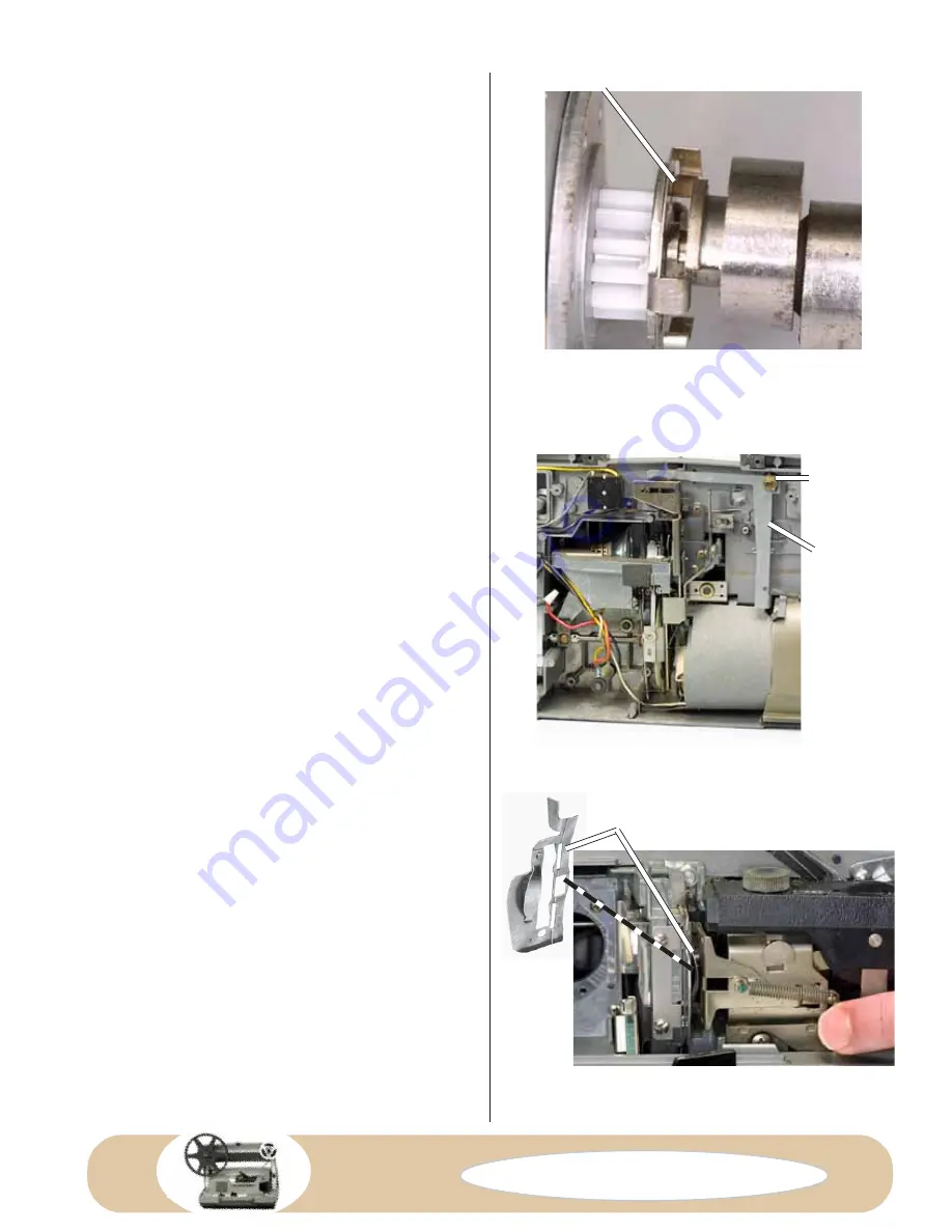
BENT SPRING BLOCKING SHUTTER-DRIVE SHAFT
FIG. D115 Shutter-drive shaft and shutter—
here a bent spring at the back of the shutter is
preventing the shutter-drive shaft from moving
to the reverse position.
FIG. D116 Back of projector.
FIG. D117 Front of projector—pressure plate
installed.
PRESSURE PLATE
FORWARD/
REVERSE
ARM
ECCENTRIC
Compliments of:
www.KodakParts.com
Содержание Instamatic M Series
Страница 50: ...Compliments of www KodakParts com...
Страница 51: ...Compliments of www KodakParts com...
Страница 52: ...Compliments of www KodakParts com...
Страница 53: ...Compliments of www KodakParts com...
Страница 54: ...Compliments of www KodakParts com...
Страница 55: ...Compliments of www KodakParts com...
Страница 56: ...Compliments of www KodakParts com...


