39
Figure 9-8
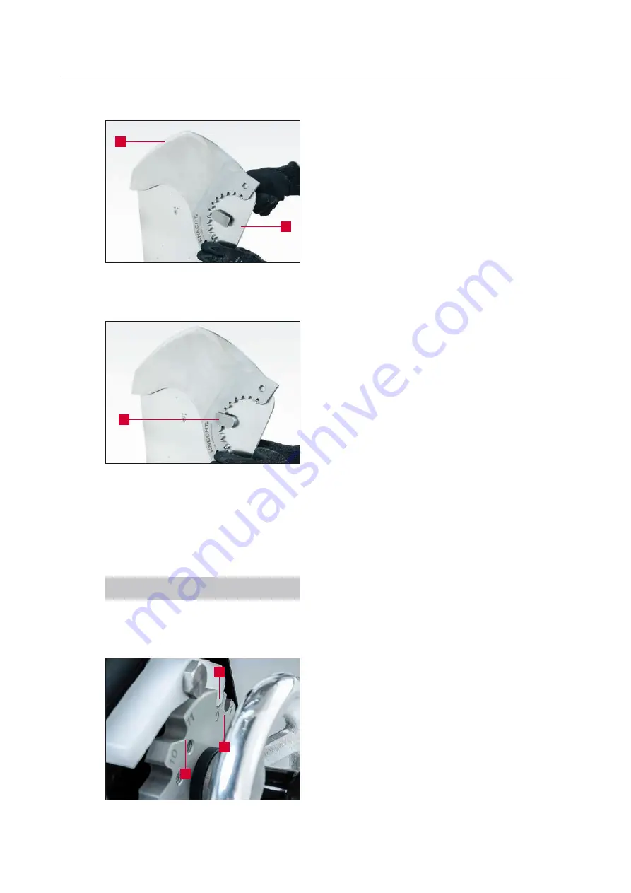
Clamping the knife onto the grind-
ing plate
2
1
Clamp the knife (9-8/1) onto the grinding plate
(9-8/2).
Turn clamping lever (9-9/1) to “Closed” position.
The knife is now locked.
Swivel the grinding plate with the clamped knife
forward to the grinding belt.
9.1.5 Basic function of the HV 261 locking mechanism
NOTE
The locking disc has several locking positions.
The first two positions are U-shaped, all
subsequent positions are V-shaped.
The two U-shaped locking positions are used to
adjust the knife on the grinding belt and to grind
the burr.
The V-shaped locking positions are used for
convex grinding of the knife.
0 = adjustment position (9-10/1)
1 = grinding position (9-10/2)
2 – 11 = convex grinding (9-10/3)
Figure 9-9
Locking the knife on the grinding
plate
1
Figure 9-10
Locking disc
2
1
3
9. Operating the HV 261


