


130
15. Electronic Function
15.1 Abbreviation
T1: Indoor room temperature
T2: Coil temperature of indoor heat exchanger
T3: Coil temperature of condenser
T4: Outdoor ambient temperature
T5: Compressor discharge temperature
Td: Target temperature
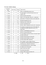
15.2 Display function
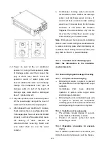
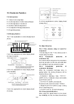
15.2.1 Icon explanation on indoor display board
(Duct)
OPERATION TIMER DEF./FAN
ALARM
Temporary button
Operation lamp
Timer indicator
Infrared signal receiver
Alarm indicator
PRE-DEF indicator(cooling and heating type)
or fan only indicator(cooling only type)
MANUAL
Display digital tube
15.2.2 Icon explanation on indoor display board
(Compact cassette).
15.2.3 Icon explanation on indoor display board
(slim Cassette).
15.2.4 Icon explanation on indoor display board
(Console).
15.2.5 Icon explanation on indoor display board
(Ceiling Floor)
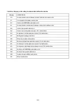
15.3 Main Protection
15.3.1 Three minutes delay at restart for
compressor
1 minute delay for the 1
st
time stand-up and 3
minutes delay for others.
15.3.2
Temperature
protection
of
compressor top
The unit will stop working when the compressor
top temp. protector cut off, and will restart after
the compressor top temp. protector restart.
15.3.3
Temperature
protection
of
compressor discharge
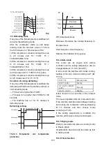
When the compressor discharge temp. is
getting higher, the running frequency will be
limited as below rules:
---Compressor discharge temp. T5>115
℃
(239°F) for 5s, compressor stops and restarts
up till T5<90
℃
(194°F)
---110<T5<115
℃
(239°F), decrease the
frequency to the lower level every 2 minutes.
---105(221°F)<T5<110
℃
(230°F), keep running
at the current frequency.
----T5<105
℃
(221°F), no limit for frequency.
15.3.4 Fan speed malfunction
When indoor fan speed keeps too low (lower
than 300RPM) for 50s, the indoor fan will shut
Содержание KDIP012-H2
Страница 8: ...5 2 2 Part names of Indoor Outdoor units Cassette Units ...
Страница 9: ...6 KDIR Duct Units ...
Страница 10: ...7 KDIP Duct Units ...
Страница 11: ...9 Ceiling floor Units ...
Страница 12: ...10 HESP DUCT Units ...
Страница 19: ...19 2 3 4 7 Outside Water Pump for Optional When Ceiling Installation ...
Страница 31: ...33 KSIE024 H220 O KSIR036 H218 inch 37 2 16 1 31 9 40 6 26 5 15 9 ...
Страница 34: ...36 Ceiling floor Units ...
Страница 39: ...41 KTIR036 H2G1 KTIR048 H2G1 ...
Страница 40: ...43 KUIR18 H2 KUIR24 H2 ...
Страница 41: ...44 KFUF036 H2G1 KFUF048 H2G1 ...
Страница 42: ...45 KFUF060 H2G1 ...
Страница 43: ...46 KFUF036 H2G1 KFUF048 H2G1 ...
Страница 44: ...47 KDIP090 H2 KDIP012 H2 KDIP018 H2 KDIP24 H2 ...
Страница 69: ...74 6 2 Outdoor Unit KSIE018 H220 O KSIE024 H220 O ...
Страница 70: ...75 KSIE009 H221 O KSIE012 H220 O ...
Страница 71: ...77 KSIR036 H218 ...
Страница 77: ...83 KDIR09 H2 Code 0 Code 1 Code 2 Code 3 Code 4 ...
Страница 78: ...84 KDIR12 H2 Code 0 Code 1 Code 2 Code 3 Code 4 ...
Страница 79: ...85 KDIR18 H2 Code 0 Code 1 Code 2 Code 3 Code 4 ...
Страница 80: ...86 KDIR24 H2 Code 0 Code 1 Code 2 Code 3 Code 4 ...
Страница 96: ...104 12 Field Wiring 9K 24K 36K 48K 60K ...
Страница 97: ...105 ...
Страница 147: ...155 P U P V ...
Страница 148: ...156 P W P N ...
Страница 174: ...184 4 Remove the evaporator support board 5 Screw off the fixing screws to remove the evaporator 4 screws 1 screw ...
Страница 181: ...191 4 Remove the evaporator fixing clamps to disassemble the evaporator Fixing clamps 1 screw ...
Страница 188: ...221 5 Remove the four fixing screws of the fan motor then remove the motor 5 ...
Страница 201: ...234 6 Remove the grounding screw 7 Remove the Wires 1 2 3 or L1 L2 S Then remove the electronic control box 7 5 ...