


112
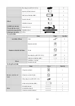
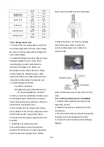
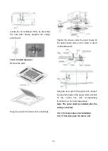
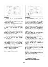
13.2.3.2 Install the main body
Fix the hook with tapping screw onto the
wall
Hang the indoor unit on the hook.
(The bottom of body can touch with floor or
suspended, but the body must install vertically.)
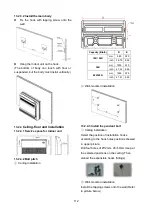
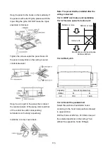
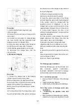
13.2.4
Ceiling-floor unit installation
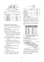
13.2.4.1 Service space for indoor unit
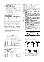
13.2.4.2 Bolt pitch
①
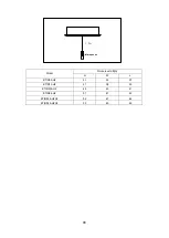
Ceiling installation
Capacity (Btu/h)
D
E
18K / 24K
mm
983
220
inch 38.70 8.66
36K
mm 1200 220
inch 47.24 8.66
48K/60K
mm 1565 220
inch 61.61 8.66
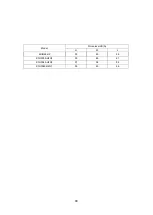
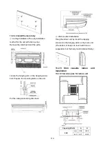
②
Wall-mounted installation
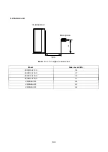
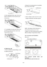
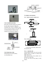
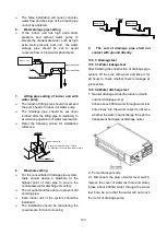
13.2.4.3 Install the pendant bolt
①
Ceiling installation
Select the position of installation hooks
according to the hook holes positions showed
in upper picture.
Drill four holes of Ø12mm, 45~50mm deep at
the selected positions on the ceiling. Then
embed the expansible hooks (fittings).
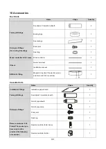
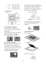
②
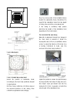
Wall-mounted installation
Install the tapping screws onto the wall.(Refer
to picture below)
Содержание KDIP012-H2
Страница 8: ...5 2 2 Part names of Indoor Outdoor units Cassette Units ...
Страница 9: ...6 KDIR Duct Units ...
Страница 10: ...7 KDIP Duct Units ...
Страница 11: ...9 Ceiling floor Units ...
Страница 12: ...10 HESP DUCT Units ...
Страница 19: ...19 2 3 4 7 Outside Water Pump for Optional When Ceiling Installation ...
Страница 31: ...33 KSIE024 H220 O KSIR036 H218 inch 37 2 16 1 31 9 40 6 26 5 15 9 ...
Страница 34: ...36 Ceiling floor Units ...
Страница 39: ...41 KTIR036 H2G1 KTIR048 H2G1 ...
Страница 40: ...43 KUIR18 H2 KUIR24 H2 ...
Страница 41: ...44 KFUF036 H2G1 KFUF048 H2G1 ...
Страница 42: ...45 KFUF060 H2G1 ...
Страница 43: ...46 KFUF036 H2G1 KFUF048 H2G1 ...
Страница 44: ...47 KDIP090 H2 KDIP012 H2 KDIP018 H2 KDIP24 H2 ...
Страница 69: ...74 6 2 Outdoor Unit KSIE018 H220 O KSIE024 H220 O ...
Страница 70: ...75 KSIE009 H221 O KSIE012 H220 O ...
Страница 71: ...77 KSIR036 H218 ...
Страница 77: ...83 KDIR09 H2 Code 0 Code 1 Code 2 Code 3 Code 4 ...
Страница 78: ...84 KDIR12 H2 Code 0 Code 1 Code 2 Code 3 Code 4 ...
Страница 79: ...85 KDIR18 H2 Code 0 Code 1 Code 2 Code 3 Code 4 ...
Страница 80: ...86 KDIR24 H2 Code 0 Code 1 Code 2 Code 3 Code 4 ...
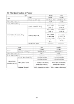
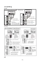
Страница 96: ...104 12 Field Wiring 9K 24K 36K 48K 60K ...
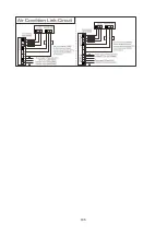
Страница 97: ...105 ...
Страница 147: ...155 P U P V ...
Страница 148: ...156 P W P N ...
Страница 174: ...184 4 Remove the evaporator support board 5 Screw off the fixing screws to remove the evaporator 4 screws 1 screw ...
Страница 181: ...191 4 Remove the evaporator fixing clamps to disassemble the evaporator Fixing clamps 1 screw ...
Страница 188: ...221 5 Remove the four fixing screws of the fan motor then remove the motor 5 ...
Страница 201: ...234 6 Remove the grounding screw 7 Remove the Wires 1 2 3 or L1 L2 S Then remove the electronic control box 7 5 ...