


118
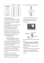
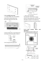
For horizontal refrigerant pipe, the distance
between supporters should not be exceed
1m.
For vertical refrigerant pipe, the distance
between supporters should not be exceed
1.5m.
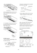
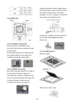
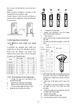
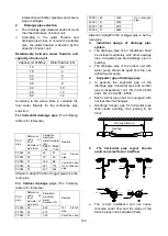
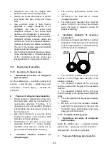
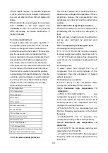
13. Connect the pipe to indoor unit and
outdoor unit by using two spanners.
Be sure to use two spanners and proper
torque to fasten the nut, too large torque
will damage the flare, and too small torque
may cause leakage. Refer the following
table for different pipe connection.
Pipe
Diameter
Torque
Sketch map
(kgf.cm)
(N.cm)
1/4" (6.35)
144~176 1420~1720
3/8" (9.52)
333~407 3270~3990
1/2" (12.7)
504~616 4950~6030
5/8" (15.9)
630~770 6180~7540
3/4" (19)
990~1210 9270~11860
13.4.3 First-Time Installation
Air and moisture in the refrigerant system
cause the following problems:
●
Increases in system pressure
●
Increases in operating current
●
Decreases in cooling and heating efficiency
●
Blocks in capillary tubing caused by
moisture in the refrigerant circuit freezing
●
Corrosion of parts in the refrigerant system
caused by water
The indoor units and the pipes between
indoor and outdoor units must be tested for
leakages and evacuated to remove gas and
moisture from the system.
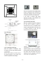
Gas leak check with soap water:
Apply soap water or a liquid neutral
detergent on the connections with a soft brush
to check for leakage in the pipe connecting
points. If bubbles emerge, the pipes are
leaking.
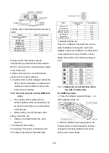
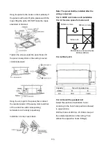
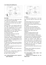
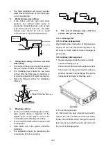
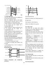
1. Air Purging Using the Vacuum Pump
1) Completely tighten the flare nuts on the
indoor and outdoor units. Confirm that both
the2-way and 3-way valves are set to the
closed position.
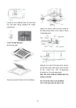
2) Connect the charge hose with the push pin
of the Handle Lo to the 3-way valve gas
service port.
3) Connect the charge hose of the Handle Hi
to the vacuum pump.
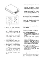
4) Fully open the Handle Lo of the manifold
valve.
5) Turn on the vacuum pump to begin
evacuation.
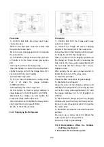
6) Conduct a 30-minute evacuation. Check
whether the compound meter indicates
-0.1Mpa(14.5Psi). If the meter does not
indicate -0.1Mpa(14.5Psi) after 30 minutes
has elapsed, continue evacuation for 20
more minutes. If the pressure does not
reach -0.1Mpa(14.5Psi) after 50 minutes
has elapsed, check if there are any leaks.
Fully close the Handle Lo valve of the manifold
valve and turn off the vacuum pump. After 5
minutes, confirm that the gauge needle is not
moving.
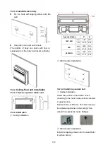
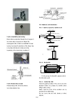
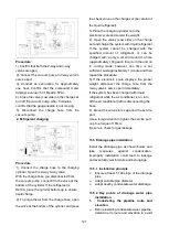
7) Turn the flare nut on the 3-way valve45°
counterclockwise for 6-7 seconds. Once
gas begins to come out, tighten the flare nut.
Make sure the pressure display on the
pressure indicator is higher than
atmospheric pressure. Then remove the
charge hose from the 3-way valve.
8) Fully open the 2-wayand 3-way valves and
securely tighten the cap on the 3-way valve.
Содержание KDIP012-H2
Страница 8: ...5 2 2 Part names of Indoor Outdoor units Cassette Units ...
Страница 9: ...6 KDIR Duct Units ...
Страница 10: ...7 KDIP Duct Units ...
Страница 11: ...9 Ceiling floor Units ...
Страница 12: ...10 HESP DUCT Units ...
Страница 19: ...19 2 3 4 7 Outside Water Pump for Optional When Ceiling Installation ...
Страница 31: ...33 KSIE024 H220 O KSIR036 H218 inch 37 2 16 1 31 9 40 6 26 5 15 9 ...
Страница 34: ...36 Ceiling floor Units ...
Страница 39: ...41 KTIR036 H2G1 KTIR048 H2G1 ...
Страница 40: ...43 KUIR18 H2 KUIR24 H2 ...
Страница 41: ...44 KFUF036 H2G1 KFUF048 H2G1 ...
Страница 42: ...45 KFUF060 H2G1 ...
Страница 43: ...46 KFUF036 H2G1 KFUF048 H2G1 ...
Страница 44: ...47 KDIP090 H2 KDIP012 H2 KDIP018 H2 KDIP24 H2 ...
Страница 69: ...74 6 2 Outdoor Unit KSIE018 H220 O KSIE024 H220 O ...
Страница 70: ...75 KSIE009 H221 O KSIE012 H220 O ...
Страница 71: ...77 KSIR036 H218 ...
Страница 77: ...83 KDIR09 H2 Code 0 Code 1 Code 2 Code 3 Code 4 ...
Страница 78: ...84 KDIR12 H2 Code 0 Code 1 Code 2 Code 3 Code 4 ...
Страница 79: ...85 KDIR18 H2 Code 0 Code 1 Code 2 Code 3 Code 4 ...
Страница 80: ...86 KDIR24 H2 Code 0 Code 1 Code 2 Code 3 Code 4 ...
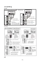
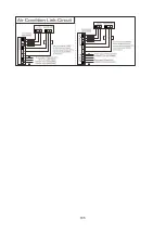
Страница 96: ...104 12 Field Wiring 9K 24K 36K 48K 60K ...
Страница 97: ...105 ...
Страница 147: ...155 P U P V ...
Страница 148: ...156 P W P N ...
Страница 174: ...184 4 Remove the evaporator support board 5 Screw off the fixing screws to remove the evaporator 4 screws 1 screw ...
Страница 181: ...191 4 Remove the evaporator fixing clamps to disassemble the evaporator Fixing clamps 1 screw ...
Страница 188: ...221 5 Remove the four fixing screws of the fan motor then remove the motor 5 ...
Страница 201: ...234 6 Remove the grounding screw 7 Remove the Wires 1 2 3 or L1 L2 S Then remove the electronic control box 7 5 ...