


108
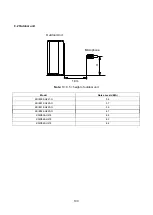
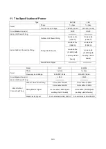
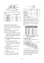
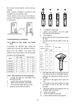
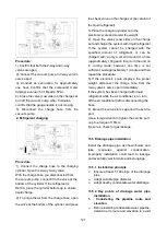
5.Please refer to the following static pressure to
install.
Model
Static Pressure(Pa)
KDIR09-H2
KDIR12-
H2
0-45
KDIR18-H2
0-70
KDIR24-H2
0-100
KDIP018-H2
0-100
KDIP24-H2
0-160
KDIR036-H2G1
0-160
KDIR048-H2G1
0-160
Change the fan motor static pressure
corresponding to external duct static pressure.
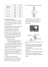
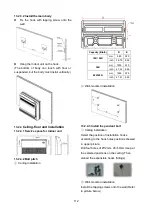
NOTE: 1.Do not put the connecting duct weight
on the indoor unit.
2.When connecting duct, use inflammable
canvas tie-in to prevent vibrating.
3. Insulation foam must be wrapped outside the
duct to avoid condensate. An internal duct
underlayer can be added to reduce noise,
if the end-user requires.
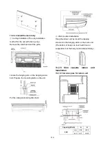
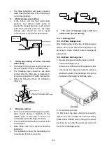
13.2.1.5 Control (only for inverter KDIR Duct
units)
The capacity of the system and the
network address of the air-conditioner can
be set by the switches on the indoor Main
Control Board.
Before setting, turn off the power. After
setting, restart the unit.
Setting is not allowed when the unit is
power on.
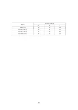
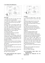
1. Horsepower code setting
The capacity of the indoor unit has been set
in the factory according to the below table.
ENC1
Toggle switch
Code
Capacity(kw)
Note: The
capacity has
been set in the
factory, anyone
can’t adjust it
except the
qualified person
4
5.3
5.6
5
7.1
7
9.0
8
10.5
9
14
16
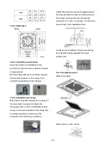
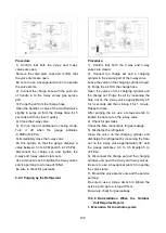
2. Network address set
Every air-conditioner in network has only one
network address to distinguish each other.
Address code of air-conditioner in LAN is set by
code switches S1 & S2 on the Main Control
Board of the indoor unit, and the set range is
0-63.
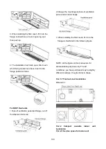
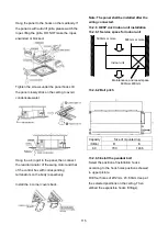
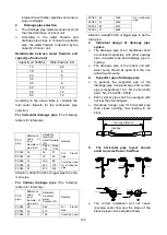
13.2.1.6
Adjust the air inlet direction (From
rear side to under-side)
For KDIR Duct units
①
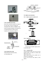
Take off ventilation panel and flange, cut
off the staples at side rail
2. Stick the attached seal sponge as per the
indicating place in the following fig, and then
change the mounting positions of air return
panel and air return flange.
Содержание KDIP012-H2
Страница 8: ...5 2 2 Part names of Indoor Outdoor units Cassette Units ...
Страница 9: ...6 KDIR Duct Units ...
Страница 10: ...7 KDIP Duct Units ...
Страница 11: ...9 Ceiling floor Units ...
Страница 12: ...10 HESP DUCT Units ...
Страница 19: ...19 2 3 4 7 Outside Water Pump for Optional When Ceiling Installation ...
Страница 31: ...33 KSIE024 H220 O KSIR036 H218 inch 37 2 16 1 31 9 40 6 26 5 15 9 ...
Страница 34: ...36 Ceiling floor Units ...
Страница 39: ...41 KTIR036 H2G1 KTIR048 H2G1 ...
Страница 40: ...43 KUIR18 H2 KUIR24 H2 ...
Страница 41: ...44 KFUF036 H2G1 KFUF048 H2G1 ...
Страница 42: ...45 KFUF060 H2G1 ...
Страница 43: ...46 KFUF036 H2G1 KFUF048 H2G1 ...
Страница 44: ...47 KDIP090 H2 KDIP012 H2 KDIP018 H2 KDIP24 H2 ...
Страница 69: ...74 6 2 Outdoor Unit KSIE018 H220 O KSIE024 H220 O ...
Страница 70: ...75 KSIE009 H221 O KSIE012 H220 O ...
Страница 71: ...77 KSIR036 H218 ...
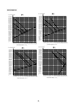
Страница 77: ...83 KDIR09 H2 Code 0 Code 1 Code 2 Code 3 Code 4 ...
Страница 78: ...84 KDIR12 H2 Code 0 Code 1 Code 2 Code 3 Code 4 ...
Страница 79: ...85 KDIR18 H2 Code 0 Code 1 Code 2 Code 3 Code 4 ...
Страница 80: ...86 KDIR24 H2 Code 0 Code 1 Code 2 Code 3 Code 4 ...
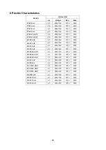
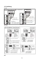
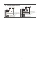
Страница 96: ...104 12 Field Wiring 9K 24K 36K 48K 60K ...
Страница 97: ...105 ...
Страница 147: ...155 P U P V ...
Страница 148: ...156 P W P N ...
Страница 174: ...184 4 Remove the evaporator support board 5 Screw off the fixing screws to remove the evaporator 4 screws 1 screw ...
Страница 181: ...191 4 Remove the evaporator fixing clamps to disassemble the evaporator Fixing clamps 1 screw ...
Страница 188: ...221 5 Remove the four fixing screws of the fan motor then remove the motor 5 ...
Страница 201: ...234 6 Remove the grounding screw 7 Remove the Wires 1 2 3 or L1 L2 S Then remove the electronic control box 7 5 ...