


F
Draw bar
Draw nut
U
V
Draw pipe
E
L1
B
D
C
5mm
L2
H
J
R
Q
P
N
G
M
T
N
N
S
K
Draw pipe
Draw bar
Chuck
Cylinder
Back plate
A(HW-08)
A(HW-10〜15)
L1
5mm
Clearance
L2
・When other actuators are operated by the same hydraulic pressure source as the cylinder for chuck, be sure that
a pressure drop of the cylinder does not occur during use. A hydraulic pressure drop leads to a drop in the
gripping force which could allow the work to fly out.
・As to the drain hose
・Use a transparent vinyl hose for visualization.
・Provide a stream slope, without air pocket. This will ensure no back pressure.
・The end of the hose is physically above the oil level. (Refer to Fig.15)
・If the hydraulic oil stagnates inside the cylinder, oil leakage occurs, which may cause a fire.
25
26
8-2. Manufacturing of the draw bar and the draw pipe
・Especially, when a large sized hydraulic unit is used, excessive surge pressure is generated and the gripping
force becomes large, therefore, it may result in breakage of the chuck or the lowering of endurance. Restrain the
surge pressure by adopting a throttle valve, etc.
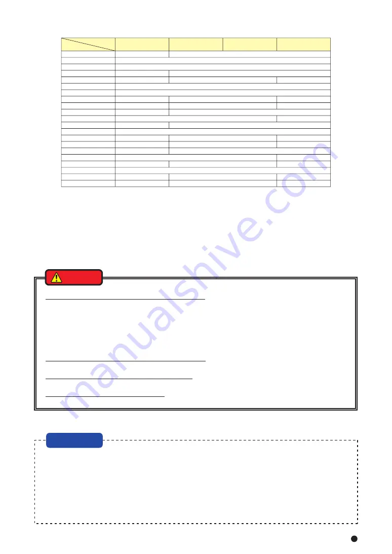
Type
HW-08
Cylinder
B
C
D
E
F
G
H
J
K
M
N
P min.
Q max.
R
S
T
U
V
L1
L2
HW-10
HW-12
HW-15
Item
Table 9
Unit: mm
・Install after removing the dust inside the pipe completely.
・Add a filter to the pressure supply line. If foreign matters gets inside the cylinder, this is dangerous since the
rotation valve of the cylinder will seize, the hose will tear off, and the cylinder will rotate. This is also dangerous
as the work will fly out.
・Always use a flexible hose for the hydraulic piping to the cylinder, and the bending force or tensile force of the
pipe must not be applied to the cylinder. Use a pipe inside diameter as large as possible and keep the piping
length as short as possible.
Determine the length of the draw bar and the draw pipe as shown below.
The dimension L1 and L2 in Fig.16 are determined from the distance A between the cylinder
adapter and the back plate.
(Example) In the combination of HW-12, YW1225R, and when A=800mm, the draw bar length L1 is
to be L1 = A-12 = 800-12 = 788mm, the draw pipe length L2 is to be L2 = A+62 = 800+62 = 862mm.
At the time of the screw process of the dimension F and V, the precision is to be JIS 6H and 6h, 6g
matching the screw of the piston of the cylinder. Pay attention so that the thread parts on both ends
and the inner periphery do not swing or become unbalanced.
Fig.17
Fig.16
・The draw-bar and draw-pipe must have enough strength. If the draw-bar or draw-pipe is broken due to low
strength, a gripping force is lost instantaneously, causing the workpiece to fly out.
・The material used for draw-bar and draw-pipe must have tensile strength above 380MPa (38kgf/mm
2
).
・Whether the draw-bar and draw-pipe have enough strength for operating conditions must be judged by the
engineer who designed the draw-bar and draw-pipe.
・The dimensions and materials mentioned in this document do not guarantee that the draw-bar and draw-pipe
are not broken under any operating conditions.
・If the draw-bar or draw-pipe is screwed in inadequately, the screw is broken and a gripping force is lost
instantaneously, causing the workpiece to fly out.
・If the draw-bar or draw-pipe screw is meshed loosely, the vibration occurs or the screw is broken. If the screw is
broken, a gripping force is lost instantaneously, causing the workpiece to fly out.
・If the draw-bar or draw-pipe is unbalanced, the vibration occurs and the screw is broken, and then a gripping
force is lost instantaneously, causing the workpiece to fly out.
YW1220R
φ25
M14
34.5
22
87
φ27
-
φ34
φ32
M34×1.5
Aー27
A+49
YW1225R
φ30
-
φ32
-
30
35
M16
M20×2.5
45
40
25
φ42
φ52
φ42
M42×1.5
M42×1.5
Aー12
A+62
M20
42.5
29
39
φ65
φ55
φ42
M55×2
Aー1.5
A+72.5
-
-
NOTICE
DANGER
WARNING
DANGER
8-3. Manufacturing of the back plate
・Process the engagement diameter of the back plate after measuring the actual spindle.
・Run-out of the back plate directly affects the process precision. The end surface run-out of the back plate, spigot
joint diameter run-out must be 0.005 mm or less.
・The precision of the processing of the chuck attachment end surface of the back plate and the spigot joint
diameter can be raised by processing them after mounting to the installed machine.
・Process the chuck attachment spigot joint diameter of the back plate at the target value B-0.01 in the dimension
B of Table 10.
・Fig.18 shows the case of the JIS short taper standard.
NOTICE
Содержание HW-08
Страница 31: ......