Bolt size
Tightening torque
M 5
M 6
M 8
M10
M12
7.5 N・m
13 N・m
33 N・m
73 N・m
107 N・m
Bolt size
Tightening torque
M14
M16
M20
M22
M24
171 N・m
250 N・m
402 N・m
539 N・m
666 N・m
Handle
Draw nut
Back plate
Cover
attaching surface
Fig.20
A gap approx. 0.5mm is
made between the body
and the wedge plunger.
Chuck attaching bolt
Wedge plunger
Draw pipe
forward
end
Wedge plunger
top surface
Type
BB206
A(mm)
17.5
BB208
21.5
BB210
21.5
BB212
23
Spindle
A
31
32
・If the screw-in depth of the draw pipe to the draw nut is insufficient, the screw will break and the gripping force
will be lost instantly, which will the work to fly out.
・If the engagement of the screw of the draw pipe is loose, vibration may occur resulting in breakage of the screw,
loss of gripping force and the work flying out.
3.Connect the chuck to the draw pipe
・Remove the soft jaw and the cover of the chuck, and insert the handle to the chuck center hole, to connect to the
draw pipe while turning the draw nut.
・When connecting the draw nut and the draw pipe, do not forcibly screw them in if they cannot be screwed smoothly,
but check the inclination of the core of the screw, etc.
・Remove the eyebolt or the belt without fail after using. If the chuck is rotated with the eyebolt, etc., attached, they
may fly out and this is dangerous.
・ Always tighten the bolts at the specified torque. If the torque is insufficient or excessive, the bolt will break, which
is dangerous as the chuck or work will fly out.
・Use the bolts attached to the chuck, and do not use other bolts. However, if you must use other bolts not
provided by Kitagawa, use bolts that have at least a strength classification of 12.9 (10.9 for M22 or more) and be
sure they are long enough.
4.Attach the chuck matching to the attaching surface of the spindle (or the back plate).
・Turn the handle for connection to make a state that the chuck closely contacts the spindle attaching surface of the
lathe.
・In the case of adjusting the centering of the chuck, lightly hit the body side face with a plastic hammer.
・ Tighten the chuck attaching bolts evenly. At this time, tighten the bolts at the specified torque.
5.Adjust the position of the wedge plunger
・The appropriate position of the wedge plunger at the cylinder forward end is the position when the dimension A in
Fig.20 becomes as shown in the table below.
・At this time, check that the reference mark of the master jaw meets the line of the outside of the stroke mark. (Refer to
page 17).
・A click stop (rotation stopper) is also attached to the draw nut, so complete adjustment at the position where this
response is felt.
Table 13
6.Attach the cover and check the run-out of the chuck
・Keep the periphery run-out and the end surface run-out of the chuck at 0.02mm T.I.R or less.
・Full stroke the jaw and check that the reference mark of the master jaw is completely within the entire stroke area
(Refer to page 17).
Table 14
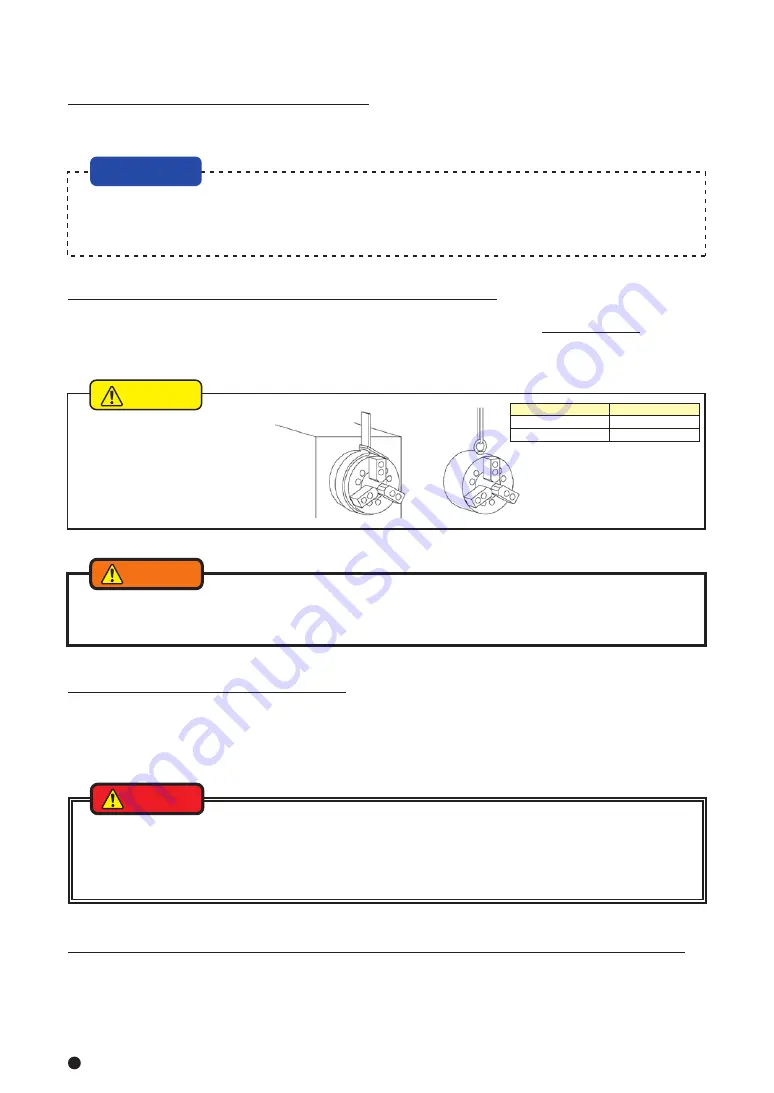
Chuck size(inch)
Eyebolt
6,8,10
12
M10
M12
・Use an eyebolt or a hanging belt
when attaching and detaching the
chuck to and from the machine,
as there is a danger of injury or
damage if the chuck drops.
2.Attach the cylinder to the spindle (or the cylinder adapter)
・Check the run-out of the cylinder, and if it is normal, attach the hydraulic pipe.
・Move 2 to 3 times at low pressure (0.4 MPa-0.5 MPa, 4 - 5 kgf/cm
2
) and set the piston at the forward end and turn off
the power supply.
CAUTION
DANGER
WARNING
DANGER
1.Attaching the draw pipe to the cylinder
・Apply adhesive onto the screw part of the draw pipe, and screw it into the piston rod of cylinder. At this time, refer to
the instruction manual for the cylinder for tightening torque.
・When attaching the draw pipe to the cylinder, the stopper pin of the piston may break if tightened at the stroke
middle position of the piston. In the case of a SS type cylinder and SR type cylinder, screw it in so that the piston
rod is fully out. Follow the explanation of the instruction manual for the cylinder for other items about the cylinder.
8−4 Attachment of chuck
NOTICE
Содержание BB200 Series
Страница 35: ......


