Bolt size
Tightening torque
M 5
M 6
M 8
M10
M12
7.5 N・m
13 N・m
33 N・m
73 N・m
107 N・m
Bolt size
Tightening torque
M14
M16
M20
M22
M24
171 N・m
250 N・m
402 N・m
539 N・m
666 N・m
Type
BB206
φA (H6)
φB
C
D (min)
φE recommended
φ140
φ104.8
76
15
φ80
BB208
BB210
φ170
φ133.4
86
17
φ103
φ220
φ171.1
95
18
φ136
BB212
φ300
φ235
102
30
φ171
φ300
φ235
102
30
φ171
φA
Spindle
Stroke stopper part
Draw pipe
Back plate
Set so that the plunger
end surface contacts
the back plate and stops.
C
D
0.005TIR
0.005TIR
φB
φE
Dimension A (spigot joint diameter) conforms to the DIN standard.
A
Cylinder adapter
Chuck
Draw pipe
Back plate
Cylinder
L
c
b
e Min
φ0.05
φ0.05
d
φ0.02
p
p
f Max
12
p
a
p
29
30
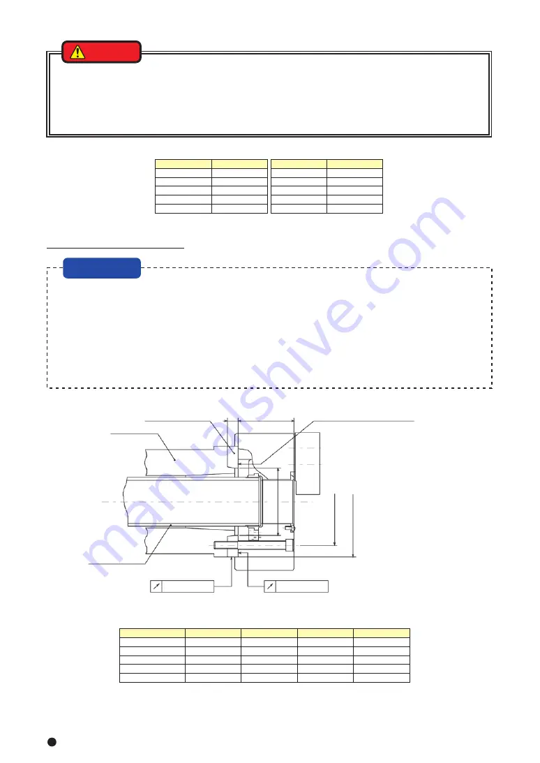
・Determine the dimension (dimension φE in Fig.17) of the back plate so that the plunger nut end surface contacts
the back plate and stops when pulling the plunger nut. If the stroke is larger than the one specified, it may cause
a chuck breakage or gripping failure.
・Process the engagement diameter of the back plate after measuring the actual spindle.
・Run-out of the back plate directly affects the process precision. The end surface run-out of the back plate, spigot
joint diameter run-out must be 0.005 mm or less.
・The precision of the processing of the chuck attachment end surface of the back plate and the spigot joint
diameter can be raised by processing them after mounting to the installed machine.
・Process the chuck attachment spigot joint diameter of the back plate at the target value A-0.01 in the dimension
A of Table 10.
・ Fig.17 shows the case of the JIS short taper standard.
Fig.17
Table 10
・Always tighten the bolts at the specified torque. If the torque is insufficient or excessive, the bolt will break, which
is dangerous as the chuck or work will fly out.
・Use the bolts attached to the chuck, and do not use other bolts. However, if you must use other bolts not
provided by Kitagawa, use bolts that have at least a strength classification of 12.9 (10.9 for M22 or more) and be
sure they are long enough.
3.Production of back plate
Table 11
8−3 In the case of with back plate
Type
Cylinder
BB206A5
BB208A6
BB210A8
BB212A1
a
M60×2
M75×2
M90×2
M115×2
b
30
35
35
35
c
25
25
30
35
d (f7)
55
70
85
110
-0.030
-0.060
-0.030
-0.060
-0.036
-0.071
-0.036
-0.071
e Min
3.5
4.5
4.5
4.5
f Max
M60×2
M75×2
M90×2
M115×2
L
A+51
A+61
A+58.5
A+69
Table 12
Also read In the case that the back plate must be manufactured in 8-2 (pages 27-29).
1.Production of draw pipe
Determine the length of the draw pipe as shown below.
The dimension L in Fig.18 is determined from the distance A between the cylinder adapter and the back plate.
(Example) In the combination of BB206, SS1543K, and when A=800mm, the draw pipe length L is to be
L = A + 51 = 800 + 51 = 851mm.
At the time of the screw process of the dimension a, the precision is to be JIS 6H and 6h, 6g matching the screw of the
piston of the cylinder. Pay attention so that the thread parts on both ends and the inner periphery do not swing or
become unbalanced.
Fig.19
Bolt size
Tightening torque
M 5
M 6
M 8
M10
M12
7.5 N・m
13 N・m
33 N・m
73 N・m
107 N・m
Bolt size
Tightening torque
M14
M16
M20
M22
M24
171 N・m
250 N・m
402 N・m
539 N・m
666 N・m
・Always tighten the bolts at the specified torque. If the torque is insufficient or excessive, the bolt will break, which
is dangerous as the chuck or work will fly out.
・Use the bolts attached to the chuck, and do not use other bolts. However, if you must use other bolts not
provided by Kitagawa, use bolts that have at least a strength classification of 12.9 (10.9 for M22 or more) and be
sure they are long enough.
Table 9
DANGER
NOTICE
WARNING
DANGER
Fig.18
SS1453K
SR1453
SS1666K
SR1566
SS1881K
SR1781
SS2110K
SR2010
Содержание BB200 Series
Страница 35: ......


