background image

Assemble units as described herein only. To do otherwise 
may result in instability. All screws, nuts and bolts must be  
tightened securely and must be checked periodically after  
assembly. Failure to assemble properly, or to secure parts 
may result in assembly failure and personal injury.

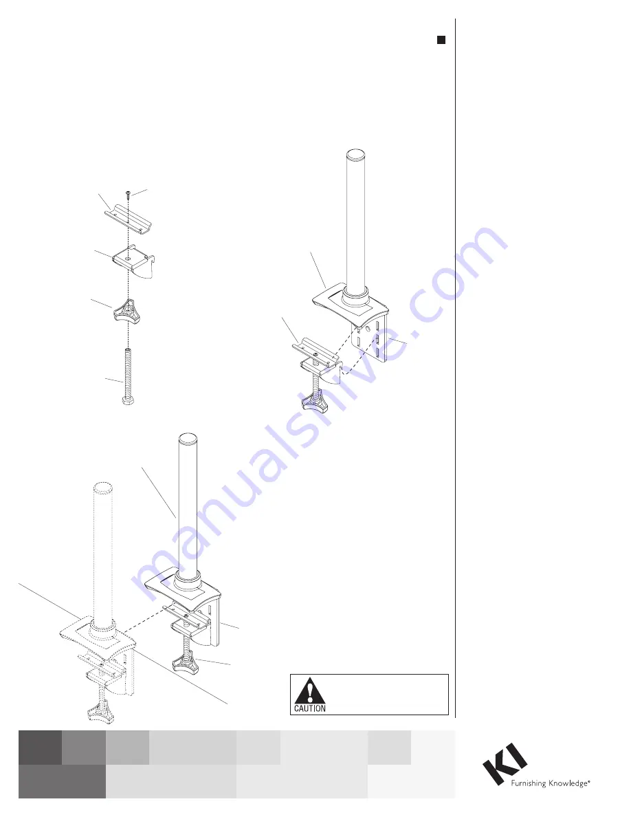
Mounting Pole to Worksurface 

using the Clamp Mounting System

Note: 

The monitor arm kit comes 

with two different length bolts, 3

1

/

2

” 

and 5

1

/

2

” long. The clamp mounting 

system detailed below uses the 3

1

/

2

” 

bolt. 

1. Insert clamp knob onto the 3

1

/

2

” long 

clamp bolt and tap the bolt head into 

the recess in the knob, ensuring the 

bolt head is securely engaged into 

the knob (Figure 1). 

2. Twist the knob with clamp bolt 

through the threaded hole in 

the lower clamp bracket. Set the 

U-shaped bracket onto the end of 

the clamp bolt, aligning the center 

hole in the bracket with the threaded 

hole in the end of the clamp bolt 

as illustrated. Using the bracket 

assembly screw provided, insert it 

through the U-shaped bracket and 

twist it into the clamp bolt. Do not 

tighten screw completely, allowing 

for the U-shaped bracket to rotate on 

the end of the clamp bolt  

(Figures 1 & 2). 

3. Hook the lower clamp bracket 

assembly into one of the top two (of 

the three) positions on the upper 

clamp bracket, appropriate to the 

worksurface thickness (Figure 2). 

4. Position the clamp bracket and 

pole assembly onto the edge of the 

worksurface at the desired location. 

Using the clamp knob, and holding 

the U-shaped bracket in position as 

illustrated, tighten to secure pole 

assembly to the worksurface  

(Figure 3).

3 / ”

clamp

bolt

1

2

clamp

knob

lower

clamp

bracket

Figure 1

U-shaped

bracket

bracket

assembly

screw

Figure 2

lower clamp

bracket

assembly

pole

assembly

upper

clamp

bracket

pole assembly

Figure 3

worksurface

clamp

bracket

clamp

knob

Assembly Instructions

Monitor Arms

Models CFS01, CFS02, CFS03, CFS04, CFS05, CFS06 & CFS07

August 2021

Содержание CFS01

Страница 1: ...with the threaded hole in the end of the clamp bolt as illustrated Using the bracket assembly screw provided insert it through the U shaped bracket and twist it into the clamp bolt Do not tighten scr...

Страница 2: ...will mount and to make sure no interference is present once installed The bracket can be oriented side to side with the flange to face the left or right table sides or front to back as long as the fla...

Страница 3: ...sition as illustrated in Detail A and a 10 wire rigid wireway is present the end of the bracket without the flange can slide above the wireway into mounting position as long as it does not interfere w...

Страница 4: ...sion arm Figure 2 3 Set bore cup and toothed locking washer into the monitor mount opening Insert joint bolt through the bore cup toothed locking washer and extension arm Figure 3 4 Insert second bore...

Страница 5: ...mbly Model CFS01 1 If pole assembly mounting systems have not been installed reference Clamp Mounting Systems instructions on page 1 or Drill Mounting Systems instructions on page 2 before continuing...

Страница 6: ...en installed Figure 1 3 Slide the dual hub support ring down the pole to the desired height of the monitor screen Twist knob on the support ring to secure in place Figure 2 4 Place the dual hub arm as...

Страница 7: ...to place back on pole once all components have been installed Figure 1 4 Slide the support ring down the pole to the desired height of the monitor screen Twist the knob on the support ring to secure i...

Страница 8: ...cable manager support ring tab Single Screen Monitor Arm Assembly Model CFS03 cont 8 Insert monitor cables through support ring tabs Figure 4 If monitor cables will be routed through optional height a...

Страница 9: ...f the pole assembly but save to place back on pole once all components have been installed Figure 1 4 Slide the support ring down the pole to the desired height of the monitor screen Twist the knob on...

Страница 10: ...cable manager monitor cable Model CFS04 extension arm assembly Figure 8 monitor cable cable manager Model CFS04 extension arm assembly Single Screen Double Extension Monitor Arm Assembly Model CFS04 c...

Страница 11: ...e cap off the pole assembly but save to place back on pole once all components have been installed Figure 1 4 Slide the dual hub support ring down the pole to the desired height of the monitor screen...

Страница 12: ...Model CFS05 arm assembly Figure 5 2 Lay cables in arm cable manager Figure 6 3 Snap cable manager back to the underside of the arm assembly taking note the text FRONT inside the cable manager Figure...

Страница 13: ...p Mounting Systems instructions on page 1 or Drill Mounting Systems instructions on page 2 before continuing Figure 1 2 If monitor mount assembly has not been installed to the dual hub arm assembly pl...

Страница 14: ...dual hub support ring pole assembly worksurface dual hub arm assembly Model CFS06 arm assembly monitor cable Dual Screen Two Double Extension Monitor Arm Assembly Model CFS06 cont 7 Insert monitor cab...

Страница 15: ...or Drill Mounting Systems instructions on page 2 before continuing Figure 1 2 If monitor mount assembly has not been installed to the extension arm assembly reference Monitor Mount Assembly to Extens...

Страница 16: ...ght of the monitor screen Twist the knob on the support ring to secure in place Figure 4 9 Place monitor mount assembly down the pole on top of the support ring Figure 4 bushing cap spacer Figure 3 ex...

Страница 17: ...of the monitor screen using the mounting screws supplied by the user Figure 1 2 Making sure the arrow symbol on the faceplate of the monitor mount assembly is facing up slide connect bracket onto face...

Страница 18: ...screws at the front and back of the arm segment as shown using the 3 16 Allen key Repeat steps until the monitor is counterbalanced Figure 2 Adjusting the Torque 1 Remove joint cap from the top of the...

Страница 19: ...19 Monitor Arms Assembly Instructions...

Страница 20: ...0 Bellevue Street P O Box 8100 Green Bay WI 54308 8100 Tel 1 800 424 2432 www ki com 2021 Krueger International Inc All Rights Reserved Code KI AI 000012R2 KI PDF 0821 Monitor Arms Assembly Instructio...

Отзывы: