background image

4

Using E4410 E-Series Power Sensors

152

Keysight N1913/1914A User’s Guide

Now, set the frequency of the signal you want to measure. The power meter 

automatically selects the appropriate calibration factor.
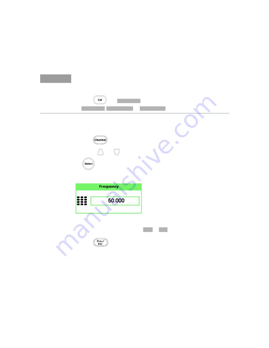
6

Press 

. On dual channel meters select the required channel.

7

Use the 

 and 

 keys to highlight the 

Frequency

 value field and press 

 to display the 

Frequency

 pop-up. Use the numeric keypad to enter the 

required value in the 

Frequency

 pop-up window.

Figure 4-3

Frequency pop-up

8

Confirm your choice by pressing 

 or 

.

9

Press 

 key to close the 

Channel Setup

 screen.


Make the measurement now.

10

Connect the power sensor to the signal to be measured. 


The corrected measurement result is displayed.

NOTE

You can reduce the steps required to carry out the zero and calibration 

procedure as follows:
– Connect the power sensor to the POWER REF output.

– Press 

 and 

. (For dual channel meters, press 

,


or 


as  required).

Zero + Cal

Zero + Cal

Zero + Cal A

Zero + Cal B

MHz

GHz

Содержание 1914A

Страница 1: ...Keysight N1913 1914A EPM Series Power Meters User s Guide...

Страница 2: ...hts customarily provided to the public to use modify reproduce release perform display or disclose commercial computer software or commercial computer software documentation No additional government r...

Страница 3: ...or for incidental or consequential damages in connection with the furnishing use or performance of this document or any information contained herein Should Keysight and the user have a separate writt...

Страница 4: ...Buyer s circuitry In addition Keysight does not warrant any damage that occurs as a result of the Buyer s circuit or any defects that result from Buyer supplied products To the extent allowed by local...

Страница 5: ...ined in FAR 2 101 a or as restricted computer software as defined in FAR 52 227 19 Jun 1987 or any equivalent agency regulation or contract clause whichever is applicable You have only those rights pr...

Страница 6: ...ts Safety Notices WARNING A WARNING notice denotes a hazard It calls attention to an operating procedure practice or the like that if not correctly performed or adhered to could result in personal inj...

Страница 7: ...ion This symbol indicates the operating switch for Stand by mode Note this instrument is NOT isolated from the mains when the switch is pressed To isolate the instrument the mains coupler mains input...

Страница 8: ...sh control Equipotentiality This symbol indicates that a device or part of a device may be susceptible to electrostatic discharges ESD which can result in damage to the product Observe ESD precautions...

Страница 9: ...by service trained personnel only Do not service or adjust alone Under certain conditions dangerous voltages may exist even with the instrument switched off To avoid electrical shock service personnel...

Страница 10: ...afety compliance IEC 61010 1 2010 EN 61010 1 2010 3rd Edition Canada CAN CSA C22 2 No 61010 1 12 USA ANSI UL 61010 1 3rd Edition EMC compliance IEC 61326 1 2005 EN 61326 1 2006 CISPR11 2003 EN 55011 2...

Страница 11: ...Canadian Standards Association This symbol is a South Korean Class A EMC Declaration This is a Class A instrument suitable for professional use and in electromagnetic environment outside of the home T...

Страница 12: ...a Monitoring and Control Instrument product The affixed product label is as shown below Do not dispose in domestic household waste To return this unwanted instrument contact your nearest Keysight Serv...

Страница 13: ...afety Information 9 Environmental Conditions 10 Regulatory Information 10 Regulatory Markings 11 Waste Electrical and Electronic Equipment WEEE Directive 2002 96 EC 12 Product category 12 Sales and Te...

Страница 14: ...Selection Option 200 53 2 General Power Meter Functions Setting the Units of Measurement 56 Setting the Measurement Frequency 57 Setting the Resolution 58 Making Relative Measurements 59 Setting Offs...

Страница 15: ...er 102 Zero Cal Lockout 103 Calibration 104 Calibration Procedure Using E Series Power Sensors and N8480 Series Power Sensors excluding Option CFT 105 Calibration Procedure Using 8480 Series Power Sen...

Страница 16: ...magnetic Compatibility EMC Measurements 143 Measurement Accuracy and Speed 144 Setting the Range 144 Measurement Considerations 145 4 Using E4410 E Series Power Sensors Introduction 148 Power Meter Co...

Страница 17: ...a Sensor Calibration Table 188 Editing Generating Sensor Calibration Tables 191 7 Using U2000 Series USB Power Sensors Introduction 196 Power Meter Configuration 197 Default Channel Setup 199 Measurem...

Страница 18: ...sage List 226 Operator Maintenance 233 Replacing the Power Line Fuse 233 Connector Maintenance 234 Contacting Keysight Technologies 235 Before calling Keysight Technologies 235 Check the Basics 236 In...

Страница 19: ...2 Power meter successfully connected via socket connection 52 Figure 2 1 Frequency pop up 57 Figure 2 2 Typical relative measurement display 59 Figure 2 3 Numeric display 60 Figure 2 4 Simplified meas...

Страница 20: ...hold measurement is performed on the HOLD block 94 Figure 2 32 Hold pop up 95 Figure 2 33 Min Hold and Max Hold measurement mode indicated in the display 95 Figure 2 34 Measurement mode in full word 9...

Страница 21: ...option 130 Figure 3 1 E9300 E Series auto averaging settings 133 Figure 3 2 E9300 E Series sensor default channel setup 134 Figure 3 3 Frequency pop up 137 Figure 3 4 Spread spectrum signal 138 Figure...

Страница 22: ...Tbls screen 192 Figure 6 12 Edit Cal display 193 Figure 6 13 Edit table title pop up 193 Figure 7 1 U2000 Series auto averaging settings 198 Figure 7 2 U2000SeriesUSBpowersensordefaultchannelsetup 199...

Страница 23: ...output setting 99 Table 2 5 Power Sensor Connection Requirements 107 Table 2 6 Equipment list 109 Table 2 7 Typical specifications 109 Table 3 1 Power sensor connection requirements 135 Table 5 1 8480...

Страница 24: ...24 Keysight N1913 1914A User s Guide THIS PAGE HAS BEEN INTENTIONALLY LEFT BLANK...

Страница 25: ...ons Used in this Guide 28 Front Panel Keys and Connections 29 The Display Layout 34 Window Symbols and Pop ups 37 Rear Panel Connections 40 Using the Instrument Web Interface 41 Making Socket Connecti...

Страница 26: ...g The N1913 1914A can be mounted in a standard 19 inch rack Rack mount kits are available as listed below Support rails are also required for rack mounting These are normally supplied with the rack an...

Страница 27: ...e the same features or capabilities The main differences are as below Specifications The specifications for the power meter are listed in Chapter 10 Characteristics and Specifications starting on page...

Страница 28: ...ess the unmarked key beside the displayed text Message This text represents a displayed message Parameter This is used to represent a parameter value or title Channel This User s Guide describes the o...

Страница 29: ...es when Local Lock Out is not enabled Press this key to select the upper or lower measurement window The selected window is highlighted by a blue line on the right side of the window Any measurement s...

Страница 30: ...menus Channel parameters such as averaging and offsets are configured from this menu Press this key to access the triggering menu The triggering feature will be made available in future for power sen...

Страница 31: ...softkeys and are referred to by the text on the display next to them For example during a Preset you are given an option to confirm the command Press to continue that is press the softkey beside the...

Страница 32: ...wn arrows are used for selecting values from a pop up list They are also used to enter text for example table names Press this key to select a highlighted field to allow data entry check a checkbox an...

Страница 33: ...3 the connector is fitted to the rear panel The Green LED beside the connector is lit when the calibrator is turned on The sensor input connectors N1914A shown the N1913A has one input If the meter is...

Страница 34: ...lds indicate ERR for any error conditions that occur or informing you to Please Zero the power sensor 2 The measured channel is shown with a 8480 Series or E Series power sensor connected 3 This field...

Страница 35: ...asurement frequency 9 The upper window is configured to show a single numeric display 10 The lower window is configured to show an analog meter which displays the measurement result and the meter scal...

Страница 36: ...dependent offset table currently selected and the measurement frequency 15 This field displays Dty Cyc if a duty cycle is set 16 This field displays Ofs if an offset is set 17 This field displays Rel...

Страница 37: ...are three different colors used to signify the pop up status Green used to allow data entry Orange used to display information Red used to display an error Warning Symbol Pop up The warning symbol is...

Страница 38: ...pears in a pop up window It may appear for example during a calibration Confirm Symbol Pop up This type of pop up window is displayed when you are required to press Confirm to verify your previous sel...

Страница 39: ...es The up down arrow keys increment and decrement the alphanumeric digit that the cursor is currently positioned The left right arrow keys move the cursor to another alphanumeric digit List Pop up Thi...

Страница 40: ...DC voltage that corresponds to the power level of the channel input 5 AC Inlet This power meter has an auto configuring power supply This allows it to operate over a range of voltages without manually...

Страница 41: ...sing the Web interface The instrument Web interface can be accessed from Keysight Connection Expert as shown in Figure 1 4 Figure 1 4 Accessing the instrument Web interface NOTE Alternatively the inst...

Страница 42: ...ort 5025 SCPI Telnet port 5024 VISA TCPIP Connect String VISA USB Connect String and GPIB address are shown Click Advanced Information to display more information about the instrument Instrument on th...

Страница 43: ...ages that may occur See Figure 1 1 See also Figure 1 7 for the example of Lan Status message Table 1 1 Type of Lan Status message IDENTIFY message to blink when the front panel identification indicato...

Страница 44: ...btain an IP address using selected LAN configuration Lan DHCP Not Available Status Running Unable to obtain IP address from DHCP server if user select DHCP configuration IP address obtained from Auto...

Страница 45: ...ides a virtual front panel interface that can be used to control the power meter remotely 1 On the left of the Welcome Page select Browser Web Control The remote front panel appears 2 Click the front...

Страница 46: ...t s LAN configuration can be viewed and modified using the Web interface On the Welcome Page click View and Modify Configuration This opens the configuration window shown in Figure 1 8 Figure 1 8 View...

Страница 47: ...N reset procedure as below Procedure Press to display the Remote Interfaces screen Press softkey to display the second page of the Remote I F menu Press softkey to reset the LAN settings to default Re...

Страница 48: ...1 Introduction 48 Keysight N1913 1914A User s Guide Figure 1 10 Changing the instrument LAN interface configuration...

Страница 49: ...lay from the Web interface 1 On the left of the Welcome Page select Get Image The screen image will be displayed 2 Right click on the image and select Save Picture As 3 Select a storage location for t...

Страница 50: ...such as word and spreadsheet applications To get the instrument data 1 On the left of the Welcome Page select Get Data The Get Data Web page will be displayed 2 Select the window measurement type of t...

Страница 51: ...ght Connection Expert Figure 1 11 Manual Configuration window 2 Click Manual Configuration on the Keysight Connection Expert window 3 Click LAN instrument 4 Enter the Hostname or IP Address and TCPIP...

Страница 52: ...1 Introduction 52 Keysight N1913 1914A User s Guide Figure 1 12 Power meter successfully connected via socket connection...

Страница 53: ...mmand from the remote interface You cannot query the SCPI version from the front panel The language selection is stored in non volatile memory and does not change when power has been off or after a re...

Страница 54: ...1 Introduction 54 Keysight N1913 1914A User s Guide THIS PAGE HAS BEEN INTENTIONALLY LEFT BLANK...

Страница 55: ...for Average Power Measurement 79 Setting Measurement Limits 87 Single Function Measurement 92 Combined Measurement 93 Max Hold Min Hold 94 Recorder Output 97 Saving and Recalling Power Meter States 1...

Страница 56: ...to each measurement mode Press Select the unit of measurement from and Softkeys which cannot be selected in your particular mode of operation are grayed out Table 2 1 Measurement units Single channel...

Страница 57: ...parative measurements between signals Procedure Set the measurement frequency as follows 1 Press On dual channel meters select the required channel 2 Use the and keys to highlight the Frequency value...

Страница 58: ...1 0 01 0 001 dB respectively if the measurement suffix is dBm or dB 1 2 3 or 4 significant digits respectively if the measurement suffix is W or The default value is 0 01 dB 3 digits To set the resol...

Страница 59: ...tup display and the relative measurement items labeled 2 Select the window you wish to set a reference value on by pressing the key The currently selected window measurement is displayed 3 Use the and...

Страница 60: ...value displayed under Result field will change as the measured signal varies NOTE If you return the power meter to display the numeric display a Rel symbol will be displayed in the measurement window...

Страница 61: ...in the measurement path Figure 2 4 Simplified measurement path Channel Functions Window Functions Display Relative Offset Channel A Upper Window Lower Window Display Relative Offset Display Relative O...

Страница 62: ...in dB and the range is 100 dB to 100 dB The equivalent range in is from 0 0000000001 to 10000000000 A positive value compensates for a loss and a negative value compensates for a gain Procedure To ent...

Страница 63: ...in dB and the range of values is 100 dB to 100 dB A positive value compensates for a loss and a negative value compensates for a gain Procedure Enter a display offset on the currently selected window...

Страница 64: ...lue field and press to display the Display Offset pop up Use the numeric keypad to enter the required value in the Offset pop up window 6 Confirm your choice by pressing Press key to complete the offs...

Страница 65: ...an 8480 Series N8480 Series an E Series or an U2000 Series sensor is used zero and calibrate the power sensor The reference calibration factor used during the calibration is automatically set by the...

Страница 66: ...nd use the and keys to highlight the FDO Table setting field and press to display the table Figure 2 8 Frequency dependent offset tables display 2 Use the and keys to highlight one of the 10 table tit...

Страница 67: ...nect the power sensor to the signal to be measured 9 The measurement result including offset is now displayed NOTE When no data is contained in the highlighted table the key is disabled grayed out Tab...

Страница 68: ...ables currently stored in the power meter press The Frequency Dependent Offset Tables screen is displayed as shown in Figure 2 8 Editing frequency dependent offset tables requires the following steps...

Страница 69: ...g the and keys Press and use the and keys to select and change the characters in the Table Name pop up to create the name you want to use Figure 2 11 Edit table title pop up Pressing adds a new charac...

Страница 70: ...required value in the Offset pop up window Complete the entry by pressing the key Figure 2 12 Changing offset unit 3 Continue adding editing values until you have entered all the data you require 4 W...

Страница 71: ...will be applied to all the offsets in the selected table and also to the remaining nine tables To change the offset unit to dB press and To change the offset unit to press and NOTE If you measure a si...

Страница 72: ...l point indicated by x y is optional if there are non zero numbers after the decimal point For example 123478202 will be displayed as 123 478202 e 6 10000 will be displayed as 100 e 2 The format of th...

Страница 73: ...nt average mode is enabled the power meter automatically sets the number of readings averaged together to satisfy the filtering requirements for most power measurements The number of readings averaged...

Страница 74: ...urement suffix is or Procedure Set measurement averaging as follows 1 Press On dual channel meters select the required channel The current setting is shown in the Meas Avg field AUTO MAN or OFF on the...

Страница 75: ...e upon detection of a step increase or decrease in the measured power Step detection can be set in both manual and automatic measurement average modes Procedure Set step detection as follows 1 Press O...

Страница 76: ...er The power meter measures the average power of the pulsed input signal and then divides the measurement result by the duty cycle value to obtain the pulse power reading The allowable range of values...

Страница 77: ...Press to check the Duty Cycle setting field Figure 2 17 Duty cycle setting 5 Press to highlight the Duty Cycle value field and press to display the Duty Cycle pop up Use the numeric keypad to enter t...

Страница 78: ...ringing For this reason it is called pulse power and not peak power or peak pulse power In order to ensure accurate pulse power readings the input signal must be pulsed with a rectangular pulse Other...

Страница 79: ...le increasing measurement throughput by reducing overhead of communication with the controller The sweep feature allows you to make power measurement by quickly stepping through a series of frequencie...

Страница 80: ...edures 1 Connect sensor to a power source 2 Connect power meter TRIG OUT to power source TRIG IN using a BNC cable The same connection is applied for power source TRIG OUT to power meter TRIG IN Figur...

Страница 81: ...ol is displayed You can start another measurement by pressing the key is a continuous trigger mode The symbol or is displayed 7 Press to configure the remaining trigger parameters The trigger Settings...

Страница 82: ...cally enabled 9 Press and to allow a TTL level high to be produced at the rear panel TRIG OUT BNC port when the meter is triggered upon a completed measurement 10 Press and select or to set the trigge...

Страница 83: ...sending INITiate CONTinuous ON command to meter 15 Configure and set the required power sweep range and step on the power source accordingly 16 Set the power source trigger input and trigger output th...

Страница 84: ...displays as shown in Figure 2 20 4 Press The Trigger menu is displayed 5 Press softkey to configure a trigger 6 Select either or 7 Press to configure the remaining trigger parameters The trigger Setti...

Страница 85: ...te command to meter to set the operation complete bit in the Standard Event Status register when all pending device operations are completed 13 Set the meter to continuous trigger cycles by sending IN...

Страница 86: ...al where Step Number of frequency step fstart Frequency sweep s start point fstop Frequency sweep s stop point Interval Frequency step size Example When fstart 1 GHz and fstop 5 GHz with given interva...

Страница 87: ...difference measurement Figure 2 23 Limits checking applications In this application a swept frequency signal is applied to the input of the Device Under Test The power meter measures the output power...

Страница 88: ...2 3 Table 2 3 Range of values for window limits Procedure Set the limits as follows 1 Press to display the Measurement Setup menus 2 Use the and keys to highlight the Limits setting field 3 Press to...

Страница 89: ...the required value and press 7 Use the key to highlight the Maximum Limits value field 8 Press to display the Maximum Limit pop up 9 Use the numeric keys to enter the required value and press 10 Press...

Страница 90: ...ilures are displayed in the appropriate field in the measurement window on the power meter s display as shown in Figure 2 26 Figure 2 26 Limit failures This measurement has failed as the result is gre...

Страница 91: ...surement displayed in or format as follows Press to select the measurement window or measurement line you want to configure Figure 2 27 Measurement Setup showing single configuration Single Numeric Du...

Страница 92: ...913A the Channel field will be disabled as shown in Figure 2 27 1 Use the to highlight the Combination function field 2 Press to display the Function pop up and use the and to highlight Single Figure...

Страница 93: ...will be disabled as shown in Figure 2 29 Figure 2 29 Measurement Setup showing combined configuration 1 Use the to highlight the Combination function field 2 Press to display the Function pop up see...

Страница 94: ...as new minimum reading appears Max hold is the maximum of all measurements since the start time The max reading will be updated as new maximum reading appears The max hold min hold reading can be res...

Страница 95: ...2 Use the to highlight the Hold function field 3 Press to display the Hold pop up and use the and to highlight Min or Max see Figure 2 32 Figure 2 32 Hold pop up 4 Press to complete the entry 5 Press...

Страница 96: ...96 Keysight N1913 1914A User s Guide 6 Press to display the measurement window in full screen mode The measurement mode will be indicated in full word in the expanded window see Figure 2 34 Figure 2 3...

Страница 97: ...y The and softkeys allow you to manually scale the power levels to represent the 1 Vdc maximum and 0 Vdc minimum output voltage of the Recorder Output Otherwise you can set the Recorder Output to Auto...

Страница 98: ...as five options 1 2 Auto 1 Auto 2 or Off 5 Press 6 Use the key to highlight the Recorder Minimum value field 7 Press to display the Recorder Minimum pop up Figure 2 35 Recorder Minimum pop up 8 Use th...

Страница 99: ...recorder output setting dBm NOTE The recorder output can be disabled and re enabled by checking the Rec o p setting field The highest power you are going to measure is used to determine the value whi...

Страница 100: ...he Sys Inputs menu accessed by pressing the key To save a measurement setup 1 Press to display the Save Recall screen as shown in Figure 2 37 Figure 2 37 Save Recall screen 2 Using the and keys select...

Страница 101: ...39 File name pop up 3 Use and keys to modify the character on which the cursor is currently positioned 4 Use or to move to other characters 5 Use and as required 6 To confirm your choice press Recall...

Страница 102: ...ing which takes approximately 10 seconds the wait symbol is displayed Figure 2 41 Zeroing pop up When to Zero Zeroing of the power meter is recommended When a 5 oC change in temperature occurs Every 2...

Страница 103: ...ll display the message Please Zero and Cal Figure 2 42 Please zero and calibrate window When you zero the sensor the message changes to Please Cal If you calibrate the sensor before zeroing it the mes...

Страница 104: ...ou are using The N1913 1914A EPM Series Power Meter User s Guide require you to set the reference calibration factor The E Series power sensors and N8480 Series power sensors excluding Option CFT set...

Страница 105: ...ensor or N8480 Series power sensor excluding Option CFT s calibration table there is no requirement to enter the reference calibration factor The power meter identifies that an E Series power sensor o...

Страница 106: ...the last value set or the default of 100 If the value is incorrect press The reference calibration factor pop up window will be displayed Use the numeric keypad to enter the required value in the pop...

Страница 107: ...sensor requires a 75 f to 50 m N Type adapter 1250 0597 to connect to the reference calibrator Remove this adapter from the power sensor input before making measurements Keysight R8486A Keysight Q848...

Страница 108: ...nput before making measurements Keysight 8487A This power sensor requires an APC 2 4 f to 50 m N Type adapter 08487 60001 to connect to the power meter Remove this attenuator before making measurement...

Страница 109: ...apters 2 4 mm f 3 5 mm m 11901D Keysight Technologies Mechanical calibration kit Type N 50 85054B Keysight Technologies Mechanical calibration kit 3 5 mm 50 85052B Keysight Technologies Mechanical cal...

Страница 110: ...Extend Port 2 of the PNA by connecting it to a 2 4 mm f to 3 5 mm f adapter via a semi rigid cable If you are verifying the 08487 60001 connect a 3 5 mm f to 2 4 mm m adapter to a semi rigid cable 6...

Страница 111: ...Device Under Test DUT Measurement 1 Leave the adapter under test in place refer to step 8 2 Record the S Parameter readings LOG_MAG for the PNA as dutS11 dutS12 dutS22 and dutS21 respectively and comp...

Страница 112: ...o blank the whole display screen The feature ensures that the meter s display is not shown to casual observers To restore the display press any buttons on the front panel To access this feature press...

Страница 113: ...password protection feature To restore the display you are required to enter the correct password Figure 2 46 Secure Blank feature To access the secure blank feature 1 Press and select 2 In the Servi...

Страница 114: ...e entered password will be displayed see Figure 2 48 Press 5 A warning message pop up will be displayed if the entered password is not 6 digits see Figure 2 49 This warning will appear for two seconds...

Страница 115: ...isplayed see Figure 2 50 You will be prompted to enter the password again for confirmation Figure 2 50 Reconfirm password 7 A warning message pop up will be displayed if the password entered is differ...

Страница 116: ...confirmation pop up 9 After screen is blanked pressing of any keys on the front panel will prompt you to enter password to restore the display see Figure 2 53 You are allowed up to three attempts of p...

Страница 117: ...3 Enter password to restore display NOTE If you have forgotten the 6 digit password and need to operate the meter immediately perform the Memory Erase operation This operation will erase all data stor...

Страница 118: ...re helps to prolong the usage hours when the meter is running under battery power To access this feature press and select In the Service menu press and select Figure 2 54 Backlight intensity control P...

Страница 119: ...l be initialized to the default settings These features can only be activated via the front panel The memory erase feature can be invoked when you forget the 6 digit password set during secure blank T...

Страница 120: ...Secure Erase 1 Press and select In the Service menu select see Figure 2 57 Figure 2 57 Secure Erase 2 A confirmation pop up will be displayed press to begin secure erase see Figure 2 58 Figure 2 58 C...

Страница 121: ...General Power Meter Functions 2 Keysight N1913 1914A User s Guide 121 3 A warning pop up will be displayed to inform you that the secure erase is in progress see Figure 2 59 Figure 2 59 Warning pop up...

Страница 122: ...This VGA output feature is available as an orderable option The VGA output ON OFF selection is provided via the front panel and SCPI The default setting is OFF To access the VGA output selection 1 Pr...

Страница 123: ...start ON All the states entered through the front panel or remote interface will be saved The power meter will be powered on with the states before it was powered off Warm start OFF The power meter wi...

Страница 124: ...pop up message will be displayed when the power meter is powered under battery power or if the AC power is lost while the power meter is still connected to an AC source applicable for power meters wi...

Страница 125: ...ser s Guide 125 Figure 2 63 Battery indicator Battery Menu For power meters with battery option to access the battery menu 1 Press and select 2 In the Service menu press and select Figure 2 64 Battery...

Страница 126: ...dvise you to power down the meter once the battery temperature is under or above the rated temperature Figure 2 65 Battery status display Low Power Battery Condition When the power meter is running on...

Страница 127: ...ight menu When backlight is turned OFF pressing on any of the keys on the front panel will turn ON the backlight These features are intended for saving power and longer usage when the meter is running...

Страница 128: ...fore the power meter indicates the battery is charging Storage temperature limits 20 C to 60 C 80 RH Failing Battery The battery can be charged and discharged numerous times but due to battery chemist...

Страница 129: ...ocal country regulatory requirements on the disposal of Lithium ion Li ion batteries Power Meter Model Sensor LCD Backlight ON Sensor LCD Backlight OFF No Sensor LCD Backlight ON No Sensor LCD Backlig...

Страница 130: ...rt default setting to Long or an error will occur when the power sensor is connected To access the cable setting 1 Press and select 2 In the Service menu press and select to toggle between the short o...

Страница 131: ...Meter Configuration 133 Measurement Accuracy 135 Measuring Spread Spectrum and Multitone Signals 138 Measuring TDMA Signals 141 Electromagnetic Compatibility EMC Measurements 143 Measurement Accuracy...

Страница 132: ...average of complex modulation formats across a wide dynamic range irrespective of signal bandwidth Further refinements are included to improve power handling allowing accurate measurement of high lev...

Страница 133: ...s 4 dBm 10 dBm Sensor Power Minimum Sensor Dynamic Range 10 dBm 2 dBm 1 2 3 4 1 1 1 4 Resolution Setting Number of Averages 1 1 4 16 1 1 8 32 1 4 16 128 1 16 64 128 Maximum 40 dBm 50 dBm 20 dBm 30 dBm...

Страница 134: ...User s Guide Default Channel Setup When an E Series E9300 power sensor is connected the following Channel Setup is automatically configured Carrying out a Preset returns the power meter to this config...

Страница 135: ...les improved measurement accuracy This section describes making average power measurements using the E9300 E Series power sensors Making a measurement requires the following steps 1 Zero and calibrate...

Страница 136: ...ed Now set the frequency of the signal you want to measure The power meter automatically selects the appropriate calibration factor 6 Press On dual channel meters select the required channel 7 Use the...

Страница 137: ...ency pop up 8 Confirm your choice by pressing or 9 Press key to close the Channel Setup screen 10 Proceed to make the measurement 11 Reconnect any required attenuators or adaptors and connect the powe...

Страница 138: ...gnal is shown in Figure 3 4 Figure 3 4 Spread spectrum signal The diode pair attenuator diode pair architecture of the E9300 E Series power sensors is ideally suited to the average power measurement o...

Страница 139: ...e between the two values stops changing The CW sensor in Figure 3 5 uses correction factors to correct for power levels beyond its square law operating region Figure 3 5 Wideband CDMA error of E Serie...

Страница 140: ...y response as shown in Figure 3 7 This is ideal for amplifier intermodulation distortion measurements where the components of the two tone or multitone test signal can be separated by hundreds of MHz...

Страница 141: ...noise immunity and allows large physical distances between power sensor and power meter Additional averaging helps reduce noise susceptibility Achieving Stable Results with TDMA Signals The averaging...

Страница 142: ...equency PRF close to a multiple or a submultiple of the 440 Hz chopper amplifier signal generate a beat note at a frequency between the PRF and 4F400Hz0 Hz Control over the filter settings is again re...

Страница 143: ...rbations Radioelectriques requirements and electromagnetic interference EMI test applications such as the radiated immunity test IEC61000 4 3 DC coupling of the E9304A input allows excellent low frequ...

Страница 144: ...ngs LOWER and UPPER The LOWER range uses the more sensitive path and the UPPER range uses the attenuated path in the E9300 E Series power sensors The default is AUTO In AUTO the range crossover value...

Страница 145: ...a good starting point it is not ideal for all measurements Signal conditions such as crest factor or duty cycle may cause the power meter to select a range which is not the optimum configuration for...

Страница 146: ...r selects the low power path in the E Series E9300 power sensor With auto averaging also configured minimal filtering is applied Values of 1 to 4 for average power levels above 20 dBm are used in the...

Страница 147: ...ters User s Guide 147 4 Using E4410 E Series Power Sensors Introduction 148 Power Meter Configuration 149 Measurement Accuracy 151 This chapter describes how to use your E4410 E Series power sensors w...

Страница 148: ...h speed power sensors and do not incorporate narrow bandwidth averaging used in average power sensors Signals with digital pulse or other forms of amplitude modulation may introduce measurement errors...

Страница 149: ...er Also the power meter automatically configures the averaging as shown in Figure 4 1 Figure 4 1 E Series CW sensor auto averaging settings 10 dB 10 dB Maximum Sensor Power Minimum Sensor Power Power...

Страница 150: ...A User s Guide Default Channel Setup When an E Series E4410 power sensor is connected the following Channel Setup is automatically configured Carrying out a Preset returns the channel to this configur...

Страница 151: ...bration factors enables you to achieve improved measurement accuracy This section describes making continuous wave measurements using the E4410 E Series power sensors Making a measurement requires the...

Страница 152: ...the numeric keypad to enter the required value in the Frequency pop up window Figure 4 3 Frequency pop up 8 Confirm your choice by pressing or 9 Press key to close the Channel Setup screen Make the me...

Страница 153: ...0 Series Power Sensors Introduction 154 Power Meter Configuration 155 Measurement Accuracy 158 Frequency Specific Calibration Factors 159 Sensor Calibration Tables 163 This chapter describes how to us...

Страница 154: ...10 GHz W8486A or the 44 dBm 8482B However they do not have their calibration factors stored in EEPROM unlike all E Series and require that you use default calibration tables or manually enter the requ...

Страница 155: ...in Figure 5 1 are automatically configured Figure 5 1 8480 Series auto averaging settings 10 dB 10 dB Maximum Sensor Power Minimum Sensor Power Power Sensor Dynamic Range 10 dB 10 dB 1 2 3 4 1 1 1 8 R...

Страница 156: ...rs 156 Keysight N1913 1914A User s Guide Default Channel Setup Figure 5 2 shows the Channel Setup configured automatically Presetting returns the power meter to this configuration Figure 5 2 8480 Seri...

Страница 157: ...the power meter 8481B 8482B These power sensors are configured with an attenuator Prior to calibration this attenuator must be removed Replace the attenuator before making measurements 8485A This pow...

Страница 158: ...wo methods of using the calibration factors inputting the individual calibration factor for a frequency prior to making the measurement or using sensor calibration tables If you are making most of you...

Страница 159: ...ments in Table 5 1 and ensure the sensor is ready for connection to the Power Reference 3 Check the current reference calibration factor setting by pressing and The value is displayed under the channe...

Страница 160: ...Now set the sensor calibration factor for the frequency of the signal you want to measure 9 Check the current reference calibration factor setting by pressing The value is displayed on the Cal Fac fi...

Страница 161: ...ess to display the Cal Factor pop up Use the numeric keypad to enter the required value in the Cal Factor pop up window Figure 5 4 Calibration factor pop up window 11 Press to complete the entry 12 Co...

Страница 162: ...ower sensor to the POWER REF output 7 Press and the channel softkey to start the calibration routine The Calibrating pop up is then displayed 8 Press The value is displayed on the Cal Fac field 9 Use...

Страница 163: ...set of 9 predefined sensor calibration tables plus a 100 default table The data in these tables is based on statistical averages for a range of Keysight Technologies power sensors Your own sensor wil...

Страница 164: ...igure 5 6 Sensor table selected 3 Press to complete the selection of the calibration factor table Figure 5 7 shows which offset table is selected Figure 5 7 Frequency dependent offset indicator 4 To c...

Страница 165: ...ncy does not correspond directly to a frequency in the sensor calibration table the power meter calculates the calibration factor using linear interpolation If you enter a frequency outside the freque...

Страница 166: ...ximum of 80 frequency points To view the calibration tables currently stored in the power meter press The Sensor Tbls screen is displayed as shown in Figure 5 6 There are also ten sensor calibration t...

Страница 167: ...ou want to edit 2 Rename the table 3 Enter the frequency and offset pairs 4 Save the table Procedure First select the table you want to edit as follows 1 Press to display the Sensor Tbls screen Figure...

Страница 168: ...d keys Press and use the and keys to select and change the characters in the Table Name pop up to create the name you want to use Figure 5 11 Edit table title pop up Pressing adds a new character to t...

Страница 169: ...you have finished editing the table press to save the table NOTE A calibration factor in the range of 1 to 150 can be entered The following rules apply to naming sensor calibration tables The name mu...

Страница 170: ...1 MHz 98 4 RCF 100 3 MHz 98 4 50 MHz 100 10 MHz 99 3 100 MHz 99 8 30 MHz 98 7 2 GHz 99 100 MHz 97 8 3 GHz 98 6 300 MHz 97 5 4 GHz 98 1 GHz 97 2 5 GHz 97 7 2 GHz 96 4 6 GHz 97 4 3 GHz 93 7 GHz 97 1 4 G...

Страница 171: ...16 GHz 99 1 1 GHz 97 17 GHz 98 4 2 GHz 95 18 GHz 100 1 3 GHz 93 4 2 GHz 91 Keysight R8486A Keysight N8485A continued RCF 100 17 GHz 96 7 50 MHz 100 18 GHz 96 6 26 5 GHz 94 9 19 GHz 96 27 GHz 94 9 20 G...

Страница 172: ...93 9 28 GHz 94 2 40 GHz 92 3 29 GHz 94 5 Keysight 8485A 30 GHz 96 6 RCF 100 31 GHz 97 6 50 MHz 100 32 GHz 98 2 GHz 99 5 33 GHz 98 9 4 GHz 98 9 34 GHz 99 5 6 GHz 98 5 34 5 GHz 99 8 GHz 98 3 35 GHz 97 6...

Страница 173: ...9 40 GHz 91 4 4 GHz 98 8 41 GHz 90 6 5 GHz 98 6 42 GHz 89 9 6 GHz 98 5 43 GHz 89 1 7 GHz 98 4 44 GHz 88 1 8 GHz 98 3 45 GHz 86 9 9 GHz 98 3 46 GHz 85 8 10 GHz 98 3 47 GHz 85 4 11 GHz 98 1 48 GHz 83 2...

Страница 174: ...GHz 95 4 39 GHz 91 24 GHz 95 40 GHz 90 7 25 GHz 95 4 41 GHz 90 3 26 GHz 95 2 42 GHz 89 5 27 GHz 95 1 43 GHz 88 5 28 GHz 95 44 GHz 88 7 29 GHz 94 4 45 GHz 88 2 30 GHz 94 46 GHz 87 31 GHz 93 7 47 GHz 8...

Страница 175: ...wer Meter Configuration Changes 177 Default Channel Setup 178 N8480 Series Sensors Connection Requirements 179 N8480 Series Power Sensors excluding Option CFT 180 N8480 Series Power Sensors with Optio...

Страница 176: ...om 30 dBm to 20 dBm 1 W to 100 mW in single range Similar to the E Series power sensors the N8480 Series power sensors are also equipped with EEPROM to store sensor s characteristics such as model num...

Страница 177: ...ings shown in Figure 6 1 are automatically configured Figure 6 1 Auto averaging settings Sensor Dynamic Range Number of Averages Upper Range Lower Range Sensor Power Minimum 1 2 3 4 1 1 2 8 Resolution...

Страница 178: ...hen a N8480 Series power sensor is connected the following Channel Setup is automatically configured Presetting returns the channel to this configuration Figure 6 2 N8480 Series sensor excluding Optio...

Страница 179: ...ements N8481A N8482A These power sensors connect directly to the POWER REF N8485A This power sensor requires an APC 3 5 f to 50 m N Type adapter 08485 60005 to connect to the POWER REF Remove this ada...

Страница 180: ...the N8480 Series power sensors excluding Option CFT Making a measurement requires the following steps 1 Zero and calibrate the power meter sensor combination 2 Set the frequency for the signal you wa...

Страница 181: ...ired channel 5 Use the and keys to highlight the Frequency value field and press to display the Frequency pop up Use the numeric keypad to enter the required value in the Frequency pop up window Figur...

Страница 182: ...e making most of your measurements at a single frequency or in a narrow range of frequencies entering a specific calibration factor is a more effective method Only a minimal amount of data entry is re...

Страница 183: ...ly be found above the calibration factors table on the power sensor body 4 To change the settings press the channel The reference calibration factor pop up window is displayed as shown in Figure 6 5 U...

Страница 184: ...l Factor pop up Use the numeric keypad to enter the required value in the Cal Factor pop up window Figure 6 6 Calibration factor pop up window NOTE You can reduce the steps required to carry out the z...

Страница 185: ...To make a measurement on channel A with a power sensor which has a reference calibration factor of 99 8 and a calibration factor of 97 6 at the measurement frequency 1 Disconnect the power sensor from...

Страница 186: ...and keys to highlight the Cal Fac value field and press to display the Cal Factor pop up Use the numeric keypad to enter 97 6 in the Cal Factor pop up window 10 Press to complete the entry 11 Connect...

Страница 187: ...set of nine predefined sensor calibration tables plus a 100 default table The data in these tables is based on statistical averages for a range of Keysight Technologies power sensors Your own sensor w...

Страница 188: ...selected The Sensor Tbls screen is shown in Figure 6 8 Procedure Select sensor calibration table as follows 1 Press 2 Use the and keys to highlight one of the 20 table titles and press to highlight Fi...

Страница 189: ...7 To confirm your choice press the appropriate unit softkey 8 Connect the power sensor to the signal to be measured 9 The corrected measurement result is now displayed NOTE When no data is contained...

Страница 190: ...ibration table display NOTE When display mode is chosen the frequency you entered and the sensor table identifier is displayed in the upper window Also pressing displays the frequency you entered and...

Страница 191: ...ables currently stored in the power meter press The Sensor Tbls screen is displayed as shown in Figure 6 8 Table 6 3 Installed power sensor models NOTE Predefined sensor calibration factor table store...

Страница 192: ...ndent offset tables requires the following steps 1 Identify and select the table you want to edit 2 Rename the table 3 Enter the frequency and offset pairs 4 Save the table Procedure First select the...

Страница 193: ...d keys Press and use the and keys to select and change the characters in the Table Name pop up to create the name you want to use Figure 6 13 Edit table title pop up Pressing adds a new character to t...

Страница 194: ...you have finished editing the table press to save the table NOTE A calibration factor in the range of 1 to 150 can be entered The following rules apply to naming sensor calibration tables The name mu...

Страница 195: ...B Power Sensors Introduction 196 Power Meter Configuration 197 Measurement Accuracy 200 Electromagnetic Compatibility EMC Measurements 202 Measurement Accuracy and Speed 203 This chapter describes how...

Страница 196: ...ve power handling allowing accurate measurement of high level signals with high crest factors without incurring damage 2 to the sensor These sensors measure average RF power on a wide variety of modul...

Страница 197: ...nize an U2000 Series USB power sensor when it is connected The sensor calibration data is automatically read by the power meter The power meter also configures the auto averaging settings shown in Fig...

Страница 198: ...24 45 dBm 55 dBm 60 dBm 20 dBm Number of Averages Resolution Setting Maximum Sensor Power Within a Range U2000 1 2 4A U2000 1 2H 20 dBm 25 dBm 30 dBm 25 dBm 4 dBm 1 dBm 3 dBm 5 dBm 15 dBm 1 dBm 2 dBm...

Страница 199: ...uide 199 Default Channel Setup When an U2000 Series USB power sensor is connected the following Channel Setup is automatically configured Carrying out a Preset returns the power meter to this configur...

Страница 200: ...making average power measurements using the U2000 Series USB power sensors Making a measurement requires the following steps 1 Zero the power meter power sensor combination 2 Set the frequency for the...

Страница 201: ...nd keys to highlight the Frequency value field and press to display the Frequency pop up Use the numeric keypad to enter the required value in the Frequency pop up window Figure 7 3 Frequency pop up 6...

Страница 202: ...urbations Radioelectriques requirements and electromagnetic interference EMI test applications such as the radiated immunity test IEC61000 4 3 DC coupling of the U2004A input allows excellent low freq...

Страница 203: ...UPPER range uses the attenuated path in the U8480 Series USB thermocouple sensors The default is AUTO In AUTO the range crossover value depends on the sensor model being used CAUTION To prevent damage...

Страница 204: ...ood starting point it is not ideal for all measurements Signal conditions such as crest factor or duty cycle may cause the power meter to select a range which is not the optimum configuration for your...

Страница 205: ...he power meter selects the low power path in the U2000 1 4A sensor With auto averaging also configured minimal filtering is applied Values of one to four for average power levels above 20 dBm are used...

Страница 206: ...7 Using U2000 Series USB Power Sensors 206 Keysight N1913 1914A User s Guide THIS PAGE HAS BEEN INTENTIONALLY LEFT BLANK...

Страница 207: ...mocouple Sensors Introduction 208 Power Meter Configuration 209 Measurement Accuracy 211 Zeroing 213 Calibrating 215 Zero Cal 217 FDO Table Editing 217 Reference Manual 218 This chapter describes how...

Страница 208: ...of two models U8481A DC to 18 GHz and U8485A DC to 33 GHz The U8480 Series allows direct measurement of average RF or microwave power through the heating effect it has on a terminating load It measure...

Страница 209: ...er meter The power meter also configures the auto averaging settings shown in Figure 8 1 to suit the thermocouple sensor characteristics Figure 8 1 U8480 Series auto averaging settings NOTE These valu...

Страница 210: ...n an U8480 Series USB thermocouple sensor is connected the following Channel Setup is automatically configured Carrying out a Preset returns the power meter to this configuration The U8480 Series ther...

Страница 211: ...mocouple sensors Making a measurement requires the following steps 1 Zero the power meter power sensor combination 2 Set the frequency for the signal you want to measure 3 Make the measurement Procedu...

Страница 212: ...quency pop up 6 Confirm your choice by pressing or 7 Press key to close the Channel Setup screen 8 Proceed to make the measurement 9 Reconnect any required attenuators or adaptors and connect the ther...

Страница 213: ...le sensor via the front panel and SCPI However the N1913 1914A EPM Series power meters do not support the choosing of the zeroing type and auto zeroing for the U8480 USB thermocouple sensor When zeroi...

Страница 214: ...8 Using U8480 Series USB Thermocouple Sensors 214 Keysight N1913 1914A User s Guide Figure 8 5 Zeroing error pop up message Error messages will be logged in the Error Log in System Error List...

Страница 215: ...sensor Both internal Int and external Ext calibration is supported by the N1913 1914A EPM Series power meters Figure 8 6 Calibration type The Auto Cal state is determined by the state of the calibrat...

Страница 216: ...N1913 1914A User s Guide Figure 8 7 Calibration pop up message Should an error occur during calibration the following pop up message will appear Figure 8 8 Calibration error pop up message Error mess...

Страница 217: ...n the Zero Cal softkey is pressed zeroing and external calibration will be triggered for the U8480 USB thermocouple sensor The calibration type will not be changed The U8480 USB thermocouple sensor sh...

Страница 218: ...ice in the form of a QR code The softkey is as shown in the figure below Figure 8 10 Reference manual softkey When you press the softkey a screen containing a QR code appears Figure 8 11 QR code scree...

Страница 219: ...nce Self Test 220 Error Messages 224 Operator Maintenance 233 Connector Maintenance 234 Contacting Keysight Technologies 235 Erasing Memory Data 238 Returning Your Power Meter for Service 239 This cha...

Страница 220: ...he front panel softkey menu allows you to run individual tests whereas the remote command runs a complete series of tests as listed in Remote Testing on page 222 Front Panel Selection of Self Tests Pr...

Страница 221: ...takes place the name of the test is listed on the screen While a test is running the message Testing appears beside the name of the test As each stage of the test is completed the Testing message is...

Страница 222: ...listed on the screen While a test is running the message Testing appears beside the name of the test As each stage of the test is completed the message Testing is replaced by either the message Passed...

Страница 223: ...eries power sensors aging sense data During RTC battery test the RTC battery power level is determined by converting the ADC value of the RTC battery power level read from the FPGA to voltage level If...

Страница 224: ...ower sensor overload the error message is displayed on the status line at the top of the display In addition the errors are also written to the error queue If there are any errors in the error queue t...

Страница 225: ...replaced with error 350 Queue Overflow Any time the queue overflows the most recent error is discarded When the errors are read they are removed from the error queue This opens a position at the end o...

Страница 226: ...meter or added a parameter to a command that does not accept a parameter For example CAL 10 109 Missing parameter Fewer parameters were received than expected for the command You omitted one or more p...

Страница 227: ...was expected Check the list of parameters to verify that you have used a valid parameter type For example MEM CLE CUSTOM_1 151 Invalid string data An invalid string was received Check to see if you ha...

Страница 228: ...witch on for example averaging duty cycle or limits Trying to clear a sensor calibration table when none is selected 222 Data out of range A numeric parameter value is outside the valid range for the...

Страница 229: ...then any command which would normally return a measurement result for example FETC READ or MEAS will generate this error message 230 Data corrupt or stale Please calibrate Channel B When CAL 1 2 RCAL...

Страница 230: ...ute the command because either no power sensor is connected or it expects an E series power sensor and one is not connected 310 System error Dty Cyc may impair accuracy with ECP sensor This indicates...

Страница 231: ...235 for details of what to do with your faulty power meter 330 Self test Failed Measurement Channel Fault 330 Self test Failed Measurement Channel A Fault 330 Self test Failed Measurement Channel B Fa...

Страница 232: ...mple you may have executed a CONFigure command which does not generate data and then attempted to read data from the remote interface 430 Query DEADLOCKED A command was received which generates too mu...

Страница 233: ...on the rear panel For all voltages the power meter uses a 250 V T2 5 H 20 mm slow blow fuse with high breaking capacity Replacing the Power Line Fuse 1 Slide the fuse holder assembly from the rear pan...

Страница 234: ...he steps below are followed Select the test equipment for the lowest SWR Keep the cable length as short as possible Use good quality cables Select the appropriate connectors Keep the connectors clean...

Страница 235: ...Your Power Meter for Service on page 239 Before calling Keysight Technologies Before calling Keysight Technologies or returning the power meter for service please make the checks listed in Check the B...

Страница 236: ...ng used when the problem occurred Check that the test being performed and the expected results are within the specifications and capabilities of the power meter Check the power meter display for error...

Страница 237: ...e is based on the ISO international country code standard and is used to designate the specific country of manufacture for the individual product The same product number could be manufactured in two d...

Страница 238: ...r calibration of all data stored in it The memory data erased includes the save recall states and power on last states The following procedure explains how to do this 1 Press the key 2 Press 3 Press 4...

Страница 239: ...st 3 to 4 inches on all sides of the power meter for packing material Surround the power meter with at least 3 to 4 inches of packing material or enough to prevent the power meter from moving in the c...

Страница 240: ...9 Maintenance 240 Keysight N1913 1914A User s Guide THIS PAGE HAS BEEN INTENTIONALLY LEFT BLANK...

Страница 241: ...r Meters User s Guide 241 10 Characteristics and Specifications For the characteristics and specifications of the N1913 1914A EPM Series Power Meters refer to the datasheet at http literature cdn keys...

Страница 242: ...10 Characteristics and Specifications 242 Keysight N1913 1914A User s Guide THIS PAGE HAS BEEN INTENTIONALLY LEFT BLANK...

Страница 243: ...is subject to change without notice Always refer to the Keysight website for the latest revision Keysight Technologies 2009 2018 Edition 20 February 12 2018 Printed in Malaysia N1913 90001 N1913 90001...

Отзывы: