background image

Artisan Technology Group 

is your source for quality 

new and certified-used/pre-owned equipment

• 

FAST SHIPPING AND 

DELIVERY

• 

TENS OF THOUSANDS OF 

IN-STOCK ITEMS

•  EQUIPMENT DEMOS
• 

HUNDREDS OF 

MANUFACTURERS 

SUPPORTED

•  LEASING/MONTHLY


RENTALS

•  ITAR CERTIFIED


SECURE ASSET 

SOLUTIONS

SERVICE CENTER REPAIRS

Experienced engineers and technicians on staff 

at our full-service, in-house repair center

WE BUY USED EQUIPMENT

Sell your excess, underutilized, and idle used equipment 

We also offer credit for buy-backs and trade-ins

www.artisantg.com/WeBuyEquipment


REMOTE INSPECTION

Remotely inspect equipment before purchasing with 

our interactive website at


www.instraview.com

LOOKING FOR MORE INFORMATION? 

Visit us on the web at


www.artisantg.com


for more 

information on price quotations, drivers, technical 

specifications, manuals, and documentation

Contact us:


(888) 88-SOURCE  |  [email protected]  |  www.artisantg.com

SM

View

Instra

Содержание 8163A

Страница 1: ...service in house repair center WE BUY USED EQUIPMENT Sell your excess underutilized and idle used equipment We also offer credit for buy backs and trade ins www artisantg com WeBuyEquipment REMOTE IN...

Страница 2: ...User Guide 8163A B Lightwave Multimeter 8164A B Lightwave Measurement System 8166A B Lightwave Multichannel System...

Страница 3: ...onal government requirements beyond those set forth in the EULA shall apply except to the extent that those terms rights or licenses are explicitly required from all providers of commercial computer s...

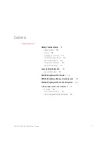
Страница 4: ...ements 19 Input Output Signals 20 Line Power Connectors 20 Instrument Markings 21 Laser Safety Information 23 Laser Safety Labels 31 8163A B Lightwave Multimeter 34 8164A B Lightwave Measurement Syste...

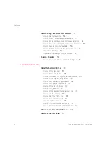
Страница 5: ...r of a Modulated Signal 58 2 Additional Information Using the System Utilities 62 How to Set the Backlight 63 How to Set the Date Time 65 How to Lock Unlock the High Power Laser Sources 67 How to Set...

Страница 6: ...de 116 How to Turn Off MinMax Mode 118 How to Hold the Screen 119 How to Use Triggers 119 Dual Power Meters Master and Slave Channels 122 4 Laser Sources How to Use Laser Source Modules 124 The Laser...

Страница 7: ...Perform a Sweep 149 How to Modulate a Signal 155 How to Use the Internal Modulation 155 How to Use External Modulation 156 How to Configure the Modulation Output 161 How to Use Triggers 163 How to Use...

Страница 8: ...on using the Keysight 81610CC Reference Cable 192 How to Measure Return Loss 198 Viewing the Calibration Values 199 A Background to Return Loss Measurement 203 Measuring the Reflected Power from a Com...

Страница 9: ...9 How to Construct a Offset Table 231 How to Use the Power Control Feature 233 Attenuator Menu Options 233 Attenuator Status Indicators 236 9 Switching Optical Routes Keysight 8159xB Optical Switch mo...

Страница 10: ...Up a Logging Function 262 Running a Logging Application 267 Analysing a Logging Application 269 On Screen Messages 273 The Stability Application 274 How to Set Up a Stability Function 275 Analysing a...

Страница 11: ...sults 307 Saving Application Measurement Results to Diskette not available on later units 310 11 Installation and Maintenance Safety Considerations 314 Initial Inspection 315 AC Line Power Supply Requ...

Страница 12: ...ce 341 Parallel Port PCMCIA Slot Keyboard connector and 24V DC Output 342 Claims and Repackaging 343 Return Shipments to Keysight Technologies 343 12 Accessories Instrument and Options Keysight 8163A...

Страница 13: ...urement System 365 Keysight 8166A Lightwave Multichannel System 366 Keysight 8166B Lightwave Multichannel System 367 Regulations Information 368 Safety Canada 368 EMC Canada 368 EMC Australia New Zeal...

Страница 14: ...roper cleaning 427 Standard Cleaning Equipment 427 Additional Cleaning Equipment 429 Preserving Connectors 432 Making Connections 432 Dust Caps and Shutter Caps 432 Immersion Oil and Other Index Match...

Страница 15: ...nstruments with an optical glass plate 443 How to clean instruments with a physical contact interface 444 Preferred Procedure 445 Procedure for Stubborn Dirt 445 How to clean instruments with a recess...

Страница 16: ...5 Contents Other Cleaning Hints 451 Making the connection 451 Lens cleaning papers 451 Immersion oil and other index matching compounds 451 Cleaning the housing and the mainframe 451 16 Firmware Upgra...

Страница 17: ......

Страница 18: ...8166B Lightwave Multichannel System In general if not specifically mentioned the information in this User Guide also applies to the previous generation of 8163A 8164A and 8166A Here you will find a qu...

Страница 19: ...he user to ensure safe operation and to maintain the product in a safe condition Safety Symbols General This is a Safety Class 1 instrument provided with a protective earth terminal and has been manuf...

Страница 20: ...closure covers panels and so on WARNING The 8163A B Lightwave Multimeter 8164A B Lightwave Measurement System and 8166A B Lightwave Multichannel System are not designed for outdoor use To prevent pote...

Страница 21: ...ervoltage category II and can operate from any single phase AC power source that supplies between 100 V and 240 V at a frequency in the range from 50 to 60 Hz The maximum power consumption is 450 VA w...

Страница 22: ...ctive earth contact Do not negate this protective action by the using an extension cord without a protective conductor Do not interrupt the protective earth connection intentionally Do not remove prot...

Страница 23: ...rk of the European Community The CSA mark is a registered trademark of the Canadian Standards Association The C Tick mark is a registered trademark of the Australian Spectrum Management Agency This te...

Страница 24: ...Modules 81650A 81651A 81652A 81654A Laser type FP Laser InGaAsP FP Laser InGaAsP FP Laser InGaAsP FP Laser InGaAsP Wavelength 15nm 1310 nm 1550 nm 1550 1625 nm 1310 1550 nm Max CW output power 1 1 8 m...

Страница 25: ...M 1M Max permissible CW output power 52 mW 163 mW 52 mW 163 mW 1 Max CW output power is defined as the highest possible optical power that the laser source can produce at its output connector Keysight...

Страница 26: ...Type EC Laser InGaAsP EC Laser InGaAsP EC Laser InGaAsP EC Laser InGaAsP Wavelength range 1450 1650 nm 1490 1640 nm 1250 1370 nm 1240 1380 nm Max CW output power 1 25 mW 25 mW 80 mW 30 mW Beam waist...

Страница 27: ...AsP Wavelength range 1455 1640 nm 1440 1640 nm 1495 1640 nm 1450 1590 nm 1370 1495 nm 1260 1375 nm 1370 1495 nm 1260 1375 nm Max CWoutput power 15mW 15mW 15mW 15mW 15mW 15mW 15mW 15mW Beamwaist diamet...

Страница 28: ...1370 1495 nm 1370 1495 nm 1460 1580 nm 1460 1580 nm 1495 1640 nm 1495 1640 nm 1260 1375 nm Max CW output power 1 15 mW 15 mW 15 mW 15 mW 15 mW 15 mW 15 mW Beam waist diameter 9 m 9 m 9 m 9 m 9 m 9 m...

Страница 29: ...1 0 1 0 1 0 1 Laser Class according to IEC 60825 1 2007 1M 1M 1M 1M 1M Max permissible CW output power 163 mW 163 mW 163 mW 163 mW 163 mW 1 Max CW output power is defined as the highest possible optic...

Страница 30: ...5 nm 1630 nm Max CW output power 1 50 mW 50 mW 50 mW Beam waist diameter 9 m 9 m 9 m Numerical aperture 0 1 0 1 0 1 Laser Class according to IEC 60825 1 2007 1M 1M 1M Max permissible CW output power2...

Страница 31: ...InGaAsP FP Laser InGaAsP Wavelength 15nm 1310 nm 1550 nm 1550 1625 nm 1310 1550 nm Max CW output power 1 1 8mW 1 8mW 1 8mW 1 8mW Beam waist diameter 9 m 9 m 9 m 9 m Numerical aperture 0 1 0 1 0 1 0 1...

Страница 32: ...Laser class 1 label Figure 1 Class 1 Safety Label Keysight 81650A 51A 52A 54A 11A 12A 13A 14A Laser class 1M label Figure 2 Class 1M Safety Label Keysight 81655A 6A 7A 81662A 3A 81600B family 81480B...

Страница 33: ...e location on the outside of the instrument where they are clearly visible to anyone using the instrument WARNING Protect yourself and pay attention to the following laser safety warnings Do not switc...

Страница 34: ...interfaces of attached fibers and termination devices to avoid burning in dust and other residue Do not leave plastic caps on the output connector or on the end of a connected fiber when you activate...

Страница 35: ...ule slots The system can host up to two front loadable modules of any combination of the following types compact Tunable Laser modules such as the the Keysight 81960A fixed wavelength Laser Sources su...

Страница 36: ...ollowing types compact Tunable Laser modules such as the the Keysight 81960A fixed wavelength Laser Sources such as the Keysight 81655A DFB Source modules such as the Keysight 81633A Power Sensors bot...

Страница 37: ...s the the Keysight 81960A fixed wavelength Laser Sources such as the Keysight 81655A DFB Source modules such as the Keysight 81663A Power Sensors both dual and single such as the Keysight 81635A Fast...

Страница 38: ...and Keysight 8166A B respectively and the names used in this manual to describe the groups of keys Figure 7 The 8164A B Lightwave Measurement System User Interface The 8163A B and the 8166A B do not...

Страница 39: ...modules or Tunable Laser modules you must enter the password to unlock the instrument If You Forget Your Password If you forget your password contact your nearest Keysight Technologies Sales Service...

Страница 40: ...e of the screen to identify each channel in the Details screen with a tab at the top of the screen to identify the channel when referencing the power measured by another channel see How to Reference A...

Страница 41: ...ightwave Multimeter this screen is shown immediately after start up It shows the most important parameters of all installed modules Figure 9 The 8163B s Overview Screen NOTE Modules with two channels...

Страница 42: ...fter start up It shows the most important parameters of all installed modules Figure 10 The 8164A B s Overview Screen Figure 11 on page 42 shows the overview screen for the 8166A B Lightwave Multichan...

Страница 43: ...Key You can move the highlighted marker between parameters using the Cursor hardkey When editing a parameter see How to Change the Value of a Parameter on page 54 the up and down cursor keys can be us...

Страница 44: ...e display When you turn the Modify Knob through one click one action is performed Turning the Modify Knob clockwise moves the highlighted marker right and then down Turning the Modify Knob anti clockw...

Страница 45: ...n or the details screen is displayed How to Access the Details Screen You can access the parameters of a module that are not shown on the overview screen by pressing Channel to select the channel and...

Страница 46: ...8163A B 8164A B 8166A B User s Guide 45 Getting Started 1 Figure 15 The 8164A B s Details Screen for a Tunable Laser Channel...

Страница 47: ...t display each channel number in the details screen The arrow indicates that undisplayed channels can be accessed by pressing the Channel hardkey To return to the overview screen press the Overview so...

Страница 48: ...8163A B 8164A B 8166A B User s Guide 47 Getting Started 1 Figure 17 The 8163B 6B Menu for a Power Sensor Channel...

Страница 49: ...r Power Sensor Channel How to Change the System Configuration Press the Config hardkey to access all the system configuration parameters that can be changed Figure 19 on page 49 and Figure 20 on page...

Страница 50: ...8163A B 8164A B 8166A B User s Guide 49 Getting Started 1 Figure 19 The 8163B System Configuration Menu...

Страница 51: ...s Guide 1 Getting Started Figure 20 The 8164A B System Configuration Menu How to Get Help Press the Help hardkey any time you need more information The instrument displays online documentation for th...

Страница 52: ...8163A B 8164A B 8166A B User s Guide 51 Getting Started 1 Figure 21 The 8164A B Help Screen Press the Index softkey to access the Index of help topics...

Страница 53: ...thin the text allow you to access relevant topics Cross references are underlined If a cross reference is highlighted it is selected Use the left or right cursor keys to move to another cross referenc...

Страница 54: ...164A B Lightwave Measurement System by pressing the Appl hardkey the Applications Menu appears as shown in Figure 23 on page 53 See Applications on page 247 for further details Figure 23 The Applicati...

Страница 55: ...ter you move to it and press the Enter hardkey press the Edit softkey press the Modify Knob if you are using the 8164A B or for numerical parameters only type a digit on the numerical keypad if you ar...

Страница 56: ...ter and then 1 Press Edit The first digit before the decimal point will be highlighted first as shown in Figure 24 Figure 24 The First Digit Before the Decimal Point is Highlighted First 4 If you want...

Страница 57: ...Press the up cursor five times to change the value of the digit to five Press Enter to end the editing How to Change a Discrete Parameter For discrete parameters you may choose a particular values wit...

Страница 58: ...If you make a mistake while you are editing a parameter you can cancel the editing and retain the previous value for the parameter by pressing the Cancel softkey If the Parameter Changes to Different...

Страница 59: ...How to Measure the Power of a Modulated Signal We want to measure the power of a 1540 nm signal modulated by a 100 kHz square wave at 500 mW 1 1 Make sure that all your connectors and connector interf...

Страница 60: ...5 How to set the wavelength for the Power Sensor module a Move to the wavelength parameter for the Power Sensor module and press Enter b Enter 1540 000 and press Enter 6 How to set the averaging time...

Страница 61: ...to set the modulated power for the Tunable Laser module a If power is not displayed in Watts move to the P parameter and press the Power Unit softkey b Move to W using the cursor key and press Enter c...

Страница 62: ...nect an External Monitor 95 How to Connect a Printer 97 This chapter describes the system functions of the 8163A B Lightwave Multimeter the 8164A B Lightwave Measurement System and the 8166A B Lightwa...

Страница 63: ...Additional Information Using the System Utilities Press the Config hardkey to access configuration information for your mainframe You see the screens in Figure 27 on page 62 and Figure 28 on page 63...

Страница 64: ...ove to any of the menu items by using the cursor key or the Modify knob Select an item by pressing Enter or the OK softkey How to Set the Backlight The Backlight and menu option allows you to change t...

Страница 65: ...1 Press the Config hardkey 2 Move to the Backlight menu option and press Enter You see a box displaying the current setting Figure 29 Entering a Backlight Value 3 Enter an integer value between zero a...

Страница 66: ...er How to Set the Date Time The instrument uses the date and time when you print out data from an application you save data to diskette from an application and you send the SYSTem DATE or SYSTem TIME...

Страница 67: ...rsor key Press Enter 5 Perform steps step 3 to step 4 again if the date is not fully correct 6 Use the cursor key to move to the Time field Press the Edit softkey The hour of the day is highlighted Th...

Страница 68: ...rdkey 2 Move to the Unlock menu option and press Enter You see a box requesting you to enter the password Figure 31 Unlocking the Instument 3 Enter the password using the softkeys or the numerical key...

Страница 69: ...should choose if you want to enable the trigger connectors Pass Through which you should choose if you want an input trigger to automatically generate an output trigger This allows you to trigger anot...

Страница 70: ...gure Startup Applications Several Applications on the 8163B and 8164B can be configured to start upwhen the system is switched on To configure startup applications 1 Press the Config hardkey 2 Move to...

Страница 71: ...ily closes an electrical contact and has a BNC type plug This accessory is similar to a mouse you press the Foot Pedal and a trigger is generated You can attach the Foot Pedal to the Input Trigger BNC...

Страница 72: ...enable the Foot Pedal or move to Off to disable the Foot Pedal 4 Press Enter NOTE The 8163A 8164A and 8166A require FPGA version 1 5 or higher The FPGA version number and date is displayed after you b...

Страница 73: ...dress menu option and press Enter You see a box displaying the current GPIB address Figure 34 Entering a GPIB Address 3 Enter an integer value between 0 and 30 into this box and press Enter The addres...

Страница 74: ...166A B User s Guide 73 Additional Information 2 How to Configure LAN User Interface Some new entries have been added to the Configuration menu which can be opened with the Config hard key Figure 35 Co...

Страница 75: ...how the Current LAN Settings Use the cursor keys or the modify knob on the 8164B to select Current LAN Settings in the Configuration Menu and press the OK soft key to open a box displaying the current...

Страница 76: ...ly in use Depending on the DHCP setting these values may be supplied by the DHCP server and differ from the values entered in the Edit LAN Settings dialog The message box does not update automatically...

Страница 77: ...er s Guide 2 Additional Information Edit LAN Settings Use the cursor keys or the modify knob on the 8164B to select Edit LAN Settings in the Configuration Menu then press the OK soft key Figure 38 Con...

Страница 78: ...8164A B 8166A B User s Guide 77 Additional Information 2 Edit the IP Address Use the cursor keys or the modify knob and the numeric keypad on the 8164B to edit the IP address Figure 39 LAN Settings IP...

Страница 79: ...t mask with the cursor keys up set one more bit down clear one more bit left clear the actual byte and jump one byte left right set all bits in the actual byte jump one byte right and set the first by...

Страница 80: ...164A B 8166A B User s Guide 79 Additional Information 2 Edit the Default Gateway Use the cursor keys or the modify knob and the numeric keypad on the 8164B to s edit the IP address Figure 41 LAN Setti...

Страница 81: ...moving the high light with the cursor keys or the modify knob on an 8164B LAN then press the Select soft key Delete the last character using the Delete soft key The OK soft key is disabled until the...

Страница 82: ...Edit Domain Name Select a character by moving the high light with the cursor keys or the modify knob on an 8164B LAN then press the Select soft key Delete the last character using the Delete soft key...

Страница 83: ...or the modify knob on the 8164B to select DHCP in the Configuration Menu and press the OK soft key to open a box that lets you enable or disable DHCP Figure 44 Configuration DHCP 2 Use the cursor key...

Страница 84: ...8163A B 8164A B 8166A B User s Guide 83 Additional Information 2 Figure 45 Enable Disable DHCP 3 Press the OK soft key...

Страница 85: ...ormation Show the MAC Address Use the cursor keys or the modify knob on the 8164B to select Show MAC Address in the Configuration Menu and press the OK soft key to open a box displaying the network ad...

Страница 86: ...8163A B 8164A B 8166A B User s Guide 85 Additional Information 2 Figure 47 MAC Address...

Страница 87: ...tion Restart the Networking If you have changed network parameters and want to apply them use the cursor keys or the modify knob on the 8164B to select Restart network in the Configuration Menu then p...

Страница 88: ...rument s serial interface 1 Press the Config hardkey 2 Move to the Serial Interface menu option and press Enter You see a box displaying all the available line speeds in bps Figure 49 Selecting a Baud...

Страница 89: ...pdate menu option and press Enter You see a box that displays Module Update mode as on 3 Press OK to start the Module Firmware Download process NOTE The Baudrate set for the serial interface of the in...

Страница 90: ...allel port on the rear panel of your mainframe see Input and Output Connectors on page 335 for a diagram of your mainframe s rear panel You can print out any of the following information a help screen...

Страница 91: ...box as shown in Figure 51 on page 90 displaying the following printer types HP PCL you can use any printer that uses the Hewlett Packard Printer Control Language Level 3 or higher and EPSON 8 pin you...

Страница 92: ...keypad and press Enter You see a box requesting you to enter the new password 4 Enter your new password It should be 4 digits long Press Enter If You Forget Your Password If you forget your password c...

Страница 93: ...rmation Figure 52 Slots with Installed Modules 3 Move to the module using the cursor key for which you require information Press Enter 4 The part number serial number and firmware revision of the chos...

Страница 94: ...6 Perform steps step 3 to step 5 to view information about other module slots or press Close to return to the configuration menu See How to Get Information About the Mainframe on page 94 for informat...

Страница 95: ...about your mainframe see Figure 54 on page 94 The manufacturer part number serial number and firmware revision of the mainframe are listed Figure 54 Viewing Information About the Mainframe 3 Press Clo...

Страница 96: ...nitor on a flat sturdy surface Before you make any connections make sure the Lightwave Measurement System and monitor are turned off Connect the power cable to the video input on the back of your moni...

Страница 97: ...96 8163A B 8164A B 8166A B User s Guide 2 Additional Information NOTE Refer to the user s guide that came with your monitor if necessary to locate your monitor s output and input ports...

Страница 98: ...compliant with Epson 8 pin printers To set up the printer perform the following steps 1 Set up your printer as described in your printer s User s Guide 2 Connect a parallel cable between your printer...

Страница 99: ......

Страница 100: ...This chapter describes how to use the 8163A B Lightwave Multimeter the 8164A B Lightwave Measurement System and the 8166A B Lightwave Multichannel System to measure optical power using a Power Meter t...

Страница 101: ...the MinMax Mode on page 116 How to Set the Number of Digits You can set the maximum number of digits that are used in power measurement This is the maximum number of digits after the decimal point To...

Страница 102: ...r dBm Values displayed in these units are derived from measurement in Watts By selecting dBm the following calculation is made Where PdBmis the power value displayed in dBm and Pinputis the input sign...

Страница 103: ...ey and press Enter How to Set the Calibration Offset This is a calibration offset that you can enter to compensate for external optical circuitry for example the 81022FF Integrating Sphere or a 3 dB c...

Страница 104: ...ted the following equations are used to calculate the power level in dB Pdisplay dB Pmeasured dBm REF dBm or Where Pdisplay is the displayed relative power Pmeasured is the absolute power level see Ho...

Страница 105: ...erence and Pmeasured is the absolute power level see How to Set the Calibration Offset on page 102 The Dsp Ref softkey is displayed if you move to a power measurement channel How to Reference Another...

Страница 106: ...oftkey 2 Move to the Ref Mode parameter and press Enter 3 Move to the channel number you want to reference using the cursor key and press Enter For example in Figure 58 on page 105 you could choose 3...

Страница 107: ...power by converting optical power to electrical power and then measuring electrical power An electrical offset is electrical power that is always present even if there no optical power is input If ele...

Страница 108: ...ETTLING is not displayed for the module channel Figure 59 Module Channels that are Setting 2 Move to the Power Meter channel and press the Menu softkey 3 Move to the Zero option to zero the current po...

Страница 109: ...is collecting light or the Power Meter receives ambient light because the input connector is uncovered Press Enter and start again at step 1 4 When the zeroing operation finishes press the Close soft...

Страница 110: ...mode ensures that the result has a displayed value between 9 and 100 of full scale The default state is for automatic ranging to be enabled Manual which allows you to set a user defined range NOTE Fo...

Страница 111: ...ge Mode If you choose Manual from the Range mode menu you must choose a range setting from the Range menu To choose a range setting follow the following steps 1 Setup the instrument 2 Move to the Powe...

Страница 112: ...d press Enter 12 Move to the Range parameter and press Enter 13 Enter the range value determined in step 8 by using the cursor key and press Enter Figure 63 Manual Range Mode Within Range If the measu...

Страница 113: ...asured power is more than 40 dBm less than the range setting it is impossible for power to be displayed The power value 1 dBm as shown in Figure 65 on page 113 is shown This means that the measured po...

Страница 114: ...5 Out of Range Power Less Than Resolution Figure 66 on page 114 shows an example of the range values you can choose for the Keysight 81634B Inn this case the values range from 10 dBm upper power limit...

Страница 115: ...s as the chosen Range decreases The resolution is always 40 dBm less than the chosen Range value The Upper Power Limit is always 3 dBm greater than the chosen Range value Table 11 Upper Power Limits a...

Страница 116: ...1 9999 mW 3 000 dBm 0 1 mW 40 000 dBm 10 dBm 199 99 mW 7 000 dBm 0 01 mW 50 000 dBm 20 dBm 19 999 mW 17 000 dBm 0 001 mW 60 000 dBm 30 dBm 1 9999 mW 27 000 dBm 0 1 nw 70 000 dBm 40 dBm 199 99 nW 37 0...

Страница 117: ...set the averaging time to 1 second 1 Move to the Power Meter channel and press the Details softkey 2 Move to the AvgTime parameter and press Enter 3 Move to 1 s by using the cursor key and press Ente...

Страница 118: ...alues of each of the previous N samples When a new measurement is taken it is added to a buffer containing the previous N samples and the oldest measurement is deleted Refresh mode which adds each new...

Страница 119: ...cursor key and press Enter The screen in Figure 68 on page 118 appears Figure 68 MinMax Mode Screen 4 Press Menu move to Data Points and press Enter 5 Enter 100 and press Enter How to Turn Off MinMax...

Страница 120: ...oftkey a second time the screen will display new measurements continuously How to Use Triggers Keysight 8163A B Series Power Meter modules allow you trigger the instrument to perform tasks and to outp...

Страница 121: ...configure the trigger connectors 2 Move to the Power Meter channel and press the Menu softkey 3 Move to Input Trigger Mode by using the cursor key and press Enter You will see the screen in Figure 70...

Страница 122: ...amming Guide How to Use Output Triggering You can configure 8163A B Series Power Meter modules to output a trigger when the instrument performs certain tasks To set your module s Output Trigger Config...

Страница 123: ...module channel 1 is the master channel and channel 2 is the slave channel The master and slave channels share the same software and hardware triggering system For some commands setting parameters for...

Страница 124: ...e 4 Laser Sources How to Use Laser Source Modules 124 This chapter describes how to use the 8163A B Lightwave Multimeter the 8164A B Lightwave Measurement System and the 8166A B Lightwave Multichannel...

Страница 125: ...his is a fixed value you can display the value but you cannot edit it Dual Wavelength Laser Source Modules Dual wavelength laser source modules have optical outputs at two wavelengths You can choose t...

Страница 126: ...using the cursor key and press Enter The green LED on the module front panel switches on To disable laser output using the user interface 1 Move to State parameter and press Enter 2 Move to Off by us...

Страница 127: ...ut Psource ATT dB Where Poutputis the power level at the output of the module Psource is the power level at the output of the source and ATTis the attenuation parameter To set the attenuation value to...

Страница 128: ...gital Modulation using Input Trigger Connector on page 159 How to Disable Modulation If Off is displayed as the Modulation Source parameter Mod Src the laser source outputs an unmodulated continuous w...

Страница 129: ...between 50 and 500 MHz typically Coherence control greatly reduces interference effects and therefore improves the power stability in sensitive test setups To enable coherence control 1 Move to the L...

Страница 130: ...wavelength source and press Enter 9 Move to Coherence Ctrl by using the cursor key and press Enter The text Mod is still displayed in the Laser Source channel 10 Enable the laser output by pressing th...

Страница 131: ...put a TTL signal at the frequency of the internal modulation of a Keysight 8163A B Series Laser Source module To set your module s Output Trigger Configuration 1 See How to Set the Trigger Configurati...

Страница 132: ...e of the following by using the cursor key Disabled the output trigger mode is disabled Modulation the output trigger connector outputs a TTL signal at the frequency of the internal modulation This si...

Страница 133: ......

Страница 134: ...How to Perform a Wavelength Sweep 147 How to Modulate a Signal 155 How to Use Triggers 163 How to Use Auxiliary Functions 167 This chapter explains how to control Tunable Laser modules from the user...

Страница 135: ...If Mod Src is Off a continuous wave signal is the chosen optical output A continuous wave signal is the default If any other Mod Src source is chosen the chosen source modulates the signal For possibl...

Страница 136: ...two optical outputs 1 Press Details 2 Move to Optical Output and press Enter 3 Use the Modify Knob to move to one of the following High Power 2 a high power optical output for example for use in tesin...

Страница 137: ...136 8163A B 8164A B 8166A B User s Guide 5 Tunable Lasers Figure 77 Setting High Power parameters...

Страница 138: ...Power Output is lit constantly and the LED beside Output 1 the Low SSE optical output flashes How to Set the Optical Output 1 Move to Output and press Enter 2 Move to your chosen optical output and p...

Страница 139: ...7 that is it is set Automatic perform the following steps a Move to Power Mode and press Enter b Move to Manual Att and press Enter The attenuation parameter Atten appears see Figure 79 on page 139 7...

Страница 140: ...ers 5 Figure 79 Setting Attenuation What is Excessive Power If the text ExP is displayed in a Tunable Laser channel see Figure 80 on page 140 you have set an output power level that is larger than the...

Страница 141: ...or the selected wavelength sweep How to Set the Laser to the Dark Position Attenuator If your tunable laser has an built in optical attenuator you can use Dark position to block all laser light from t...

Страница 142: ...e level and the output power is not calibrated Figure 81 Output Power and the Analog Output in Manual ATT Mode Attenuator If your Tunable Laser module has an attenuator installed the Analog Output sig...

Страница 143: ...m 1 Move to power parameter P and press Pwr unit You should see the power unit menu 2 Move to dBm and press Enter 3 Press Enter to edit the power value 4 Enter 10 000 and press Enter How to Set the BN...

Страница 144: ...uide to find your module s specified range Every Tunable Laser module has a permitted wavelength range This range is greater than the specified range The permitted wavelength range varies for each Tun...

Страница 145: ...the frequency offset df The formula for calculating the output wavelength is where c is the speed of light in a vacuum 2 998 108 ms 1 To set a frequency offset of 1 000 THz from a base wavelength of 1...

Страница 146: ...th How to Change the Output Wavelength 1 Move to and press Enter is the output wavelength in the equation above 2 Enter 1570 and press Enter How to Set the Base Wavelength NOTE Note how the frequency...

Страница 147: ...ve How to Change the Frequency Offset 4 Move to f and press Enter f represents the frequency offset df in the equation above 5 Enter 1 000 and press Enter The frequency offset f changes to 1 000 THz N...

Страница 148: ...velength sweep Start the wavelength at which the sweep begins Stop the wavelength at which the sweep ends Step the size of the change in the wavelength for each step of a stepped sweep Cycles the numb...

Страница 149: ...oway if you want to start every odd sweep cycle at Start and to start each even sweep cycle at Stop Select Oneway if you want to start every sweep cycle at Start and to end every sweep cycle at Stop F...

Страница 150: ...ength sweep over the range 1510 nm to 1570 nm three times sweeping two ways in 1 nm steps stopping for half a second at each wavelength step 1 Move to the Tunable Laser channel and press Details 2 Mov...

Страница 151: ...tical output 17 Press Run Swp to start the sweep The screen in Figure 86 on page 150 appears 18 The wavelength is swept automatically but you can a press Stop to end the sweep or b press Pause to paus...

Страница 152: ...ove to Sweep Mode and press Enter 3 Move to the Continuous sweep mode and press ENTER 4 Move to Start and press Enter 5 Enter 1520 000 and press Enter NOTE Continuous sweep mode is not available for a...

Страница 153: ...Finished see How to Use Output Triggering on page 165 NOTE The following table explains all possible configuration problems 368 LambdaStop LambdaStart start wavelength must be smaller than stop wavele...

Страница 154: ...ys in 1 nm steps 1 Move to the Tunable Laser channel and press Details 2 Move to Sweep Mode and press Enter 3 Move to the Manual by using the cursor key and press Enter 4 Perform step 4 to step 13 on...

Страница 155: ...154 8163A B 8164A B 8166A B User s Guide 5 Tunable Lasers Figure 88 Performing a Manual Sweep 8 Perform step 6 until you choose to press Stop...

Страница 156: ...utput Figure 89 The Modulated Signal How to Set the Output Power of a Modulated Signal To set the output power to 555 000 W 1 Move to the Tunable Laser channel and press Details softkey 2 Move to the...

Страница 157: ...l Digital Modulation using Input Trigger connector or Trigger Feedback from another module in the same mainframe Coherence Ctrl Coherence Control External Digital Modulation External digital modulatio...

Страница 158: ...ursor key and press Enter The text ExtD appears in the Tunable Laser channel External Analog Modulation External analog modulation uses a signal of up to 5 Vpp A 5 Vpp signal causes 15 modulation of t...

Страница 159: ...module as shown in Figure 92 on page 159 This enables you to fine tune the output wavelength within a limited wavelength range Wavelength locking may exhibit some hysteresis effects The wavelength ch...

Страница 160: ...ital Modulation using Input Trigger Connector External digital modulation uses a TTL level signal Apply this signal to the Input Trigger connector on the rear panel of your mainframe For information o...

Страница 161: ...ce module Set as folows Menu Modulation Source internal Menu Modulation Frequency desired value Menu Output trigger mode Modulation 2 Set all slave modules Menu Modulation Source Backplane new for DFB...

Страница 162: ...ly a good setting To enable coherence control 1 Move to the Tunable Laser channel and press Details 2 Move to Mod Src and press ENTER 3 Move to Coherence Ctrl Coherence Control to increase linewidth t...

Страница 163: ...llowing two menu items by using the cursor key FRQ RDY where the modulation signal is combined with the laser ready signal so that the output is kept low when there is no optical signal being output f...

Страница 164: ...nnector To set your module s Input Trigger Configuration 1 See How to Set the Trigger Configuration on page 68 for how to configure the trigger connectors 2 Move to the Tunable Laser channel and press...

Страница 165: ...stepped sweep to be performed Run Sweep an input trigger will start a single sweep cycle 5 Press Enter You can generate input triggers in any of the following ways applying a trigger to the Input Trig...

Страница 166: ...annel and press Menu 3 Move to Output Trigger Mode by using the cursor key and press Enter You will see the screen in Figure 94 on page 165 Figure 94 Output Trigger Mode 4 Move to one of the following...

Страница 167: ...Lasers Sweep Started a trigger is output after a sweep cycle starts 5 Press Enter NOTE If you choose Step Finished and a Continuous sweep the wavelength interval between hardware triggers is set by th...

Страница 168: ...e laser and to reduce power and this has been unsuccessful To realign the laser cavity 1 Move to the Tunable Laser channel and press Menu 2 Move to Realign and press OK You will see the screen in Figu...

Страница 169: ...ero then UNCAL is shown on the user interface in both Autocal modes No Accuracy class is shown in the Autocal Off mode The bit 6 ARA recommended is set in the questionable condition register See the 8...

Страница 170: ...81600B and earlier tunable laser instruments automatically perform a wavelength zero from time to time To avoid interruption of your measurements you should perform a wavelength zero at a time of your...

Страница 171: ...tion for Auto Lambda Zeroing setting When Auto Calibration is disabled it is possible to operate the TLS at a temperature that differs more than 4 4 K from the last Lambda Zeroing temperature In this...

Страница 172: ...h accuracy typ Class Max Temperature Deviation Absolute Relative ACC1 4 4K refer to specification ACC2 10K 8 pm 3 pm ACC3 25K 10 pm 5 pm NOTE To get the specified performance ensure the warm up time h...

Страница 173: ...sweeps there is no interruption to the measurement due to settling Also no settling will occur during operation at a fixed wavelength when at least one output is switched on By periodically checking...

Страница 174: ...s chapter explains how to use the 8163A B Lightwave Multimeter 8164A B Lightwave Measurement System or 8166A B Lightwave Multichannel System together with the modular Keysight compact Tunable Laser fa...

Страница 175: ...C band The 81960A 81940A and 81949A cover the C and L bands with high power in the L band Each module covers a total wavelength range of 110 nm The 81960A covers a range of 125 nm Module Description...

Страница 176: ...into longer fibers without the impairment to time domain measurements that can be associated with intensity amplitude modulation To use the SBS Suppression control SBS C feature Refer to Figure 97 on...

Страница 177: ...176 8163A B 8164A B 8166A B User s Guide 6 Compact Tunable Lasers Figure 97 Updated Tunable Laser channel Details including SBS Suppression...

Страница 178: ...System or 8166A B Lightwave Multichannel System to measure Return Loss Here you will find a quick explanation of the terms Return Loss and Insertion Loss a description of how to measure Return Loss an...

Страница 179: ...component is a measure of how much light the component reflects It is a ratio of the power reflected by the device to the power incident on the device More normally we talk about the return loss of a...

Страница 180: ...n external source a Laser Source module A Power Meter A typical setup using a Keysight 81610A Return Loss module where the DUT is a connector pair is described in Figure 98 on page 179 Figure 98 Measu...

Страница 181: ...urce modules See Accessories on page 345 for a list of modules that can be installed in your mainframe Refer to the note below that explains the use of highly coherent light sources Tunable Lasers whe...

Страница 182: ...clude an internal source and must be used in conjunction with a suitable external source Figure 99 The Contents of the 81610A Return Loss module 81611A and 81612A Return Loss modules 81611A and 81612A...

Страница 183: ...module They are for use in the 8163B Lightwave Multimeter the 8164A B Lightwave Measurement System and the 8166A B Lightwave Multichannel System for making return loss measurements Figure 101 The Cont...

Страница 184: ...asurements as described in Calibrating the Return Loss Module on page 188 These calibrations eliminate wavelength dependencies coupler directivity insertion losses backscattering and other non ideal c...

Страница 185: ...under test to avoid overly frequent reconnection at the instrument Setup External and Internal Sources The Return Loss measurement setup described uses A Fabry Perot laser source module inserted as a...

Страница 186: ...end of the patchcord to prevent light being coupled into the end Move to the Return Loss module channel and press Zero to remove electrical offsets in the instrument Set Averaging Time 2 Move to the...

Страница 187: ...patchcord reflections due to imperfect directivity of the internal couplers reflections at internal terminations reflections at connector ends and diodes Intuitively one could call the T value the noi...

Страница 188: ...s as follows Where Pref is the reflected power from the measurement path at the return loss diode when making a reference calibration Ppara is the backward flowing power from the measurement path at t...

Страница 189: ...nent of known reflectance The Keysight 81000BR Reference Reflector allows you to make a Reflectance Calibration and a Termination Calibration These procedures are described in Calibration using the Ke...

Страница 190: ...igure 107 on page 189 if you are using an External Source Figure 107 Reflectance Calibration External Source or Figure 108 on page 189 if you are using an internal source Figure 108 Reflection Calibra...

Страница 191: ...s correct Set RLref to the value of the return loss of the reference reflection you are using For example if you are using the Keysight 81000BR reference reflector set RLref to 0 18 dB Figure 109 Meas...

Страница 192: ...an External Source Figure 110 Termination Calibration External source or Figure 111 on page 191 if you are using an internal source Figure 111 Termination Calibration Internal Source 2 Terminate the...

Страница 193: ...asurement patchcord to make a Termination Calibration The 81610CC has an FC PC connector as reflector that has been measured and labeled at the factory The connector face should be protected and not b...

Страница 194: ...set the value the return loss value of the reference cable you are using then press OK 4 Switch on the Laser 5 Press Menu Move to Reflectance calibration and press Enter The instrument measures the po...

Страница 195: ...e 114 Power Transmitted through the Reference Cable External Source or Figure 115 on page 194 if you are using an internal source Figure 115 Power Transmitted through the Reference Cable Internal Sour...

Страница 196: ...smitted through the Measurement Patchcord External Source or Figure 117 on page 195 if you are using an internal source Figure 117 Power Transmitted through the Measurement Patchcord Internal Source 2...

Страница 197: ...g the Measurement Patchcord Use this procedure to calibrate the Return Loss module against a terminated patchcord that is when there are no reflections returning from its end 1 Making sure all the con...

Страница 198: ...end Tip You can do this by wrapping the fiber five times around the shaft of a screwdriver or some similar object with a diameter of between 5 mm and 7 mm 3 Move to Terminated calibration and press En...

Страница 199: ...Return Loss channel is the measured return loss 1 Attach the DUT to the measurement patchcord In the example shown in Figure 120 on page 198 the DUT is a connector pair Figure 120 Measuring the Return...

Страница 200: ...ged your measurement setup make the appropriate calibration measurements again 1 Press Menu Move to the Show calibration menu item The Calibration parameters screen for the Return Loss Diode appears a...

Страница 201: ...shows current value for the following quantities Para the parasitic power value measured by the Return Loss module s monitor diode in dBm This value is determined by the termination calibraion or you...

Страница 202: ...rs as displayed in Figure 124 on page 202 This screen shows current value for the following quantities FPDelta the loss correction in dB due to differences between the reference cable and the measurem...

Страница 203: ...202 8163A B 8164A B 8166A B User s Guide 7 Return Loss Measurement Figure 124 The Calibration Parameters Screens User Data...

Страница 204: ...from a Component with a Known Reflection Factor This measured power from the reflection reference is called PRef The following two components are recommended for use as a reflection reference the Key...

Страница 205: ...d measure the transmitted power Eref You can use Eref to calculate the front panel delta see Calculating the Front Panel Delta on page 209 Figure 126 Measuring the Power transmitted through the Reflec...

Страница 206: ...Power Transmitted Through the Measurement Patchcord Connect the measurement patch cord the cable you will use to connect to the Device Under Test DUT directly to a Power Meter and measure the transmi...

Страница 207: ...PDUT Measuring the Power Transmitted Through the DUT Remove the termination from the DUT and connect the DUT to a Power Meter so that the power that is transmitted through the DUT can be measured This...

Страница 208: ...the coupler and the reflections due to the measurement system That is where The constants t1 t2 k1 and k2 are multipliers giving the proportion of power transmitted through the coupler from the Input...

Страница 209: ...ion factor as RRef This gives the following equation For Measuring the Power when there are No Reflections on page 205 the value of the reflection factor is zero This gives the following equation For...

Страница 210: ...ce Calibration on page 192 with the measurement patchcord as used in How to Measure Return Loss on page 198 This is caused by differences in reflections from the front panel connector and also differe...

Страница 211: ...to the setups described in Measuring the Power Transmitted Through the Reflection Reference on page 204 and in Measuring the Power Transmitted Through the Measurement Patchcord on page 205 respective...

Страница 212: ...nsertion Loss is explained in What is Insertion Loss on page 178 To measure the insertion loss you must measure the power transmitted through the measurement cable see Measuring the Power Transmitted...

Страница 213: ......

Страница 214: ...m or 8166A B Lightwave Multichannel System together with the 8157xA family of Variable Optical Attenuator modules to attenuate and control optical power in single mode optical fibers Here you will fin...

Страница 215: ...wavelength flat The 81576A and 81577A dual slot modules incorporate a powermeter so that you can set the output power level of the attenuator directly In addition these modules feature power control f...

Страница 216: ...8163A B 8164A B 8166A B User s Guide 215 Setting Attenuation and or Power Levels 8 Figure 132 81576A 77A Attenuator module power control loop...

Страница 217: ...enuator module The User Interface The Overview Display Figure 133 on page 216 is an Overview screen taken from an 8164A B mainframe Figure 133 81570A 71A 73A Attenuator module 8164A B GUI Overview Her...

Страница 218: ...mainframe the calibration can be done manually by entering the offset value and reference power level If the Attenuator module and the reference powermeter are not hosted by the same mainframe but the...

Страница 219: ...re taken from an 8164A B mainframe The user interface for an 8163A 8163B 8166A or 8166B mainframe may display fewer elements Use the equivalent menu selection instead Number of Digits displayed To sel...

Страница 220: ...t panel is lit The Enable button Press the Enable button located on the front panel of the Attenuator module to toggle the shutter state The On Off Softkey Press the On Off softkey to toggle the shutt...

Страница 221: ...filter technology with a very low wavelength dependence Nevertheless for the best possible accuracy If the source is of a particular wavelength set the Attenuator module to that wavelength If the sour...

Страница 222: ...ting its status is shown as B or Busy How to Apply an Attenuation Offset Attenuating an input signal to a DUT introduces additional connectors and other components into your optical test setup An atte...

Страница 223: ...put to the reference powermeter input 7 Note the insertion loss measurement displayed by the powermeter 8 Select the details screen for the Attenuator 9 Use the cursor key to select the Offset paramet...

Страница 224: ...parameter You can use the PM Off softkey to offset the difference between the power measured by the internal powermeter and your reference powermeter as described Calibrating Test Setups that use an...

Страница 225: ...uator module since these modules include a filter with minimum wavelength dependency The 81576A and 81577A modules incorporate a powermeter whose responsivity varies over wavelength The module specifi...

Страница 226: ...1570A 71A 73A 78A Attenuator module first measure the power applied by your test set up to the DUT input then store this value as the Attenuator s Pref parameter After calibration you edit the Attenua...

Страница 227: ...when the Attenuator s Power Control feature is enabled the Attenuator module automatically corrects for power changes at its input to maintain your desired output power Preconditions To make the cali...

Страница 228: ...onnector losses that occur between the Attenuator module output and the DUT input After calibration you edit the Attenuator s PSET parameter to control the absolute power applied to the DUT 1 Disconne...

Страница 229: ...and Pactual 4 If the reference powermeter is hosted by another mainframe Manually enter the value of POff POff Pactual Pref where Pref is the power level measured by your reference powermeter 5 Discon...

Страница 230: ...ble On or Off The Menu item Offset is functionally equivalent to the Offset parameter Editing the Offset Table If you have previously characterized the output path 1 Press the Menu softkey 2 Set Offse...

Страница 231: ...66A B mainframe the first Offset Table entry is displayed If there are no entries the message Offset Table is Empty is displayed Figure 139 The Offset Table Figure 139shows the fourth fifth and sixth...

Страница 232: ...simplicity the following manual procedure assumes your reference powermeter is hosted by the same mainframe as the Attenuator module as described in Hosting a Reference Powermeter on page 217 For each...

Страница 233: ...tenuator status display includes Exa If the operating wavelength is between two wavelengths stored in the Offset Table the offset applied is calculated by linear interpolation The Attenuator status di...

Страница 234: ...and consequent wear on the filter motor mechanism in response to an unstable source for differences between P SET and Pactual greater than 0 01 dB but less than 0 1 dB P SET is updated approximately e...

Страница 235: ...B 8166A B User s Guide 8 Setting Attenuation and or Power Levels Figure 141 81570A 71A 73A Attenuator Menu Options 81576A 77A Menu Options Press the Menu softkey to display the window shown in Figure...

Страница 236: ...u Options Use the Cursor key to scroll to two additional options Offset and Offset Table The P actual Averaging Time Zero Zero all and Input trigger mode options are associated with the Attenuator s i...

Страница 237: ...applied Exa An exact offset has been applied Int An interpolated offset has been applied Ext An extrapolated offset has been applied PC The Power Control feature is on 81576A 77A Exp 81566A 67A 76A 7...

Страница 238: ...163A B Lightwave Multimeter 8164A B Lightwave Measurement System or 8166A B Lightwave Multichannel System together with the 8159xB family of Optical Switch modules to change optical routes during a te...

Страница 239: ...rface or multimode version option 062 with straight 50 125 m FC PC connector interface The discontinued 81591A 81591S 81592A 81592S 81594A 81594S and 81595A 81595S are fully supported by the 816xA B m...

Страница 240: ...8163A B 8164A B 8166A B User s Guide 239 Switching Optical Routes 9 Figure 143 Keysight 81595B Optical Switch module 1x4 angled contact connectors...

Страница 241: ...erface The Overview Display Figure 144 on page 240 is an Overview screen taken from an 8164A B mainframe Figure 144 Optical Switch module User Interface Overview display Here Slot 0 hosts a backloadab...

Страница 242: ...s softkey Figure 145 Optical Switch module 8164A B User Interface Details Screen Elements All the figures in this chapter are taken from an 8164A B mainframe The user interface for an 8163A 8163B 8166...

Страница 243: ...matically updates the number of the port assigned to Route B For example a 81594B 2x2 non blocking crossover switch has two routes described by Route A 1 Route B 2 and Route A 2 Route B 1 Independent...

Страница 244: ...dependent routing you cannot select a numbered port assigned to port A 3 Press OK If the switch module has dependent routing Route A is updated automatically The Edit softkey is functionally equivalen...

Страница 245: ...4 a 81591B 1x2 Optical Switch is used to select one of two different sources different wavelengths as the input to the DUT Figure 146 Laser Source selection Selecting Measurement and Calibration Paths...

Страница 246: ...al Switch is used to insert or bypass a fiber spool Figure 148 Circuit selection with crossover switch Selecting one of several DUTs in a parallel test setup In Figure 149 on page 246 two 81595B 1x4 O...

Страница 247: ...95B 1x4 Optical Switch is used to select one of up to four analysing instrument Figure 150 Test instruments selection In each case the advantages to be gained from using switch modules include speedie...

Страница 248: ...hout the possibility of any pause between measurements The Stability application logs and displays power measurements The Stability application differs from the Logging application because you may use...

Страница 249: ...applications are not available for the 8166A B Lightwave Multichannel System The Return Loss Application is only available for the 8163A B Lightwave Multimeter You can access these applications by pr...

Страница 250: ...re displayed at the bottom of the screen in units of seconds The symbol that is listed directly beneath these values displays the difference between A and B in seconds For the PACT application the wav...

Страница 251: ...r this is quicker than using the cursor keys How to Zoom In To zoom in one level around the active marker 1 Press the Next softkey until you move to your chosen marker 2 Position the marker using the...

Страница 252: ...softkey The menu appears 2 Move to Grid Off If the grid has been switched off to switch the grid on 1 Press the Menu softkey The menu appears 2 Move to Grid On How to Use Legends Legends are used to...

Страница 253: ...numerically with regard to legend number All legend texts if you have not previously edited the legend text are of the PM x y where x represents the slot number and y represents the channel number Fig...

Страница 254: ...CapsLock softkey to toggle between upper and lower case characters Press the Cancel to reject the edited legend label and return to the menu Press the OK to accept the edited legend label and return...

Страница 255: ...Applications Figure 153 Samples Display Line Samples the curve will be displayed using dots to represent each sample of the curve Depending on the zoom level you choose if these dots are very close t...

Страница 256: ...8164A B 8166A B User s Guide 255 Applications 10 Figure 154 Samples Display Samples Samples Line the curve will be displayed using both symbols for each sample of the curve and a line connecting each...

Страница 257: ...on and press Enter 3 Press the Close softkey to return to the graph How to Read Curve Values You can lock markers A or B to a curve in order to move between individual samples In this way you can read...

Страница 258: ...Press the A softkey to lock marker A to a curve The number opposite Marker A on curve is highlighted 3 Use the cursor key to move to the legend number of the curve to which you want to lock marker A 4...

Страница 259: ...Press the Menu softkey 2 Move to Unlock From Curve and press Enter to return to the graph How to Lock Unlock Markers to Samples You can choose to lock the markers to samples that is the results that a...

Страница 260: ...long the curve Figure 158 Lock the Samples Off To lock unlock markers to samples 1 Press the Menu softkey 2 Move to one of the following menu items Lock to Samples On to lock markers to samples or Loc...

Страница 261: ...260 8163A B 8164A B 8166A B User s Guide 10 Applications 3 Press Enter to return to the graph NOTE Only one of these menu items will be available for selection...

Страница 262: ...application and AvgTime the averaging time is the length of time over which a signal is averaged Longer averaging times increase the accuracy and improve the noise rejection Longer averaging times als...

Страница 263: ...ey The Applications menu as shown in Figure 160 on page 262 appears Figure 160 The Applications Menu 2 Move to Logging and press Enter The 8164A B Logging Setup Screen as shown in Figure 161 on page 2...

Страница 264: ...8163A B 8164A B 8166A B User s Guide 263 Applications 10 Figure 161 The 8164A B Logging Setup Screen...

Страница 265: ...Edit 2 To deselect a Power Meter channel move to the Power Meter as denoted by slot and channel numbers see Slot and Channel Numbers on page 39 press Unset 3 To select a Power Meter channel press Edi...

Страница 266: ...dB and press Enter See What are the Power Units on page 101 for an explanation of power units NOTE If you are using the 8164A B Lightwave Multimeter you may set all Power meter parameters from the Log...

Страница 267: ...ings is displayed For each selected Power Meter channel press Enter move to a range setting and press Enter 7 Move to Ref Mode press Enter move to one of the following referencing modes Value you set...

Страница 268: ...nter Setting Logging Parameter 9 Move to Samples press Enter enter an integer value between 1 and 4000 and press Enter 10 Move to AvgTime press Enter move to an averaging time period and press Enter R...

Страница 269: ...ts are measured Press Close to return to the Logging Measurement screen See Working with Application Graphs on page 249 for information on zooming in and out Press Cancel to return to the Logging Setu...

Страница 270: ...access the Logging Analysis screen after the logging application completes by completing the following instructions 1 You cannot access the Logging Analysis screen from the graph If you are viewing th...

Страница 271: ...270 8163A B 8164A B 8166A B User s Guide 10 Applications Figure 166 The 8164A B Logging Analysis Screen...

Страница 272: ...To edit the reference mode used for the analysis move to Ref Mode press Enter move to one of the following referencing modes Value you set a reference value using Ref see step 5 First Sample the first...

Страница 273: ...you are using the 8163A B press More the screen in Figure 168 on page 272 appears move to Stat Ch press Enter move to a Power Meter channel and press Enter Figure 168 The 8163B Logging Analysis Scree...

Страница 274: ...as reported an overrange The over ranged value is clipped statistical data is invalid NoH No Head There is an Optical Head Interface module inserted in the mainframe that does not have an Optical Head...

Страница 275: ...ates a period time a new measurement is started after the completion of every period time Period time may be greater than or equal to the averaging time you set and is always greater than or equal to...

Страница 276: ...ss Enter The Stability Setup Screen as shown in Figure 170 on page 276 appears NOTE The total time concludes after the last dwell time period not after the last averaging time period The Stability app...

Страница 277: ...276 8163A B 8164A B 8166A B User s Guide 10 Applications Figure 170 The Keysight 8164A B Stability Setup Screen...

Страница 278: ...s Edit 3 To deselect a Power Meter channel move to the Power Meter as denoted by slot and channel numbers see Slot and Channel Numbers on page 39 press Unset 4 To select a Power Meter channel press Ed...

Страница 279: ...n 7 Move to Pwr unit press Enter move to dBm W or dB and press Enter See What are the Power Units on page 101 for an explanation of power units 8 Move to press Enter enter the wavelength value of your...

Страница 280: ...range settings is displayed For each selected Power Meter channel press Enter move to a range setting and press Enter 12 Move to Ref Mode press Enter move to one of the following referencing modes Va...

Страница 281: ...the right cursor key enter a two digit time value in minutes press the right cursor key enter a two digit time value in seconds and press Enter 15 Move to AvgTime press Enter move to an averaging tim...

Страница 282: ...are measured Press Close to return to the Stability Measurement screen See Working with Application Graphs on page 249 for information on zooming in and out Press Cancel to return to the Stability Set...

Страница 283: ...ability Analysis screen after the stability application completes by completing the following instructions 20 You cannot access the Stability Analysis screen from the graph If you are viewing the grap...

Страница 284: ...8163A B 8164A B 8166A B User s Guide 283 Applications 10 Figure 175 The Keysight 8164A B Stability Analysis Screen...

Страница 285: ...To edit the reference mode used for the analysis move to Ref Mode press Enter move to one of the following referencing modes Value you set a reference value using Ref see step 24 First Sample the fir...

Страница 286: ...the Keysight 8163A B press More a screen similar to that shown in Figure 177 on page 285appears move to Stat Ch press Enter move to a Power Meter channel and press Enter Figure 177 The Keysight 8163A...

Страница 287: ...has reported an overrange The over ranged value is clipped statistical data is invalid NoH No Head There is an Optical Head Interface module inserted in the mainframe that does not have an Optical He...

Страница 288: ...configuration of the system you use you can measure insertion loss single channel power measurement over wavelength All results can be displayed on the screen printed out to hardcopy This can be a con...

Страница 289: ...e Laser module press Edit use the cursor key to move to your preferred Tunable Laser module as denoted by slot and channel numbers see Slot and Channel Numbers on page 39 and press Enter 7 Perform ste...

Страница 290: ...Enter Setting Sweep Parameters 11 Move to Start press Enter enter the start wavelength of the sweep and press Enter 12 Move to Stop press Enter enter the stop wavelength of the sweep and press Enter 1...

Страница 291: ...er ranges for each wavelength sweep The sweeps are combined using a stitching process to generate the final results This feature is useful when you wish to measure the transmission characteristics of...

Страница 292: ...the output of the high power optical output can be regulated and Both master 1 where both optical outputs can be enabled but only the output of the low SSE optical output can be regulated Press Enter...

Страница 293: ...ons Figure 179 PACT Reference Screen 19 Press New Ref A box similar to the box in Figure 180 on page 293 appears prompting you to connect a fiber to the first Power Meter channel NOTE The application...

Страница 294: ...d The wavelength shows you the current wavelength of the Tunable Laser module 21 There are two softkeys available from the PACT Reference Measurement screen Press Graph to view a graph of the Measurem...

Страница 295: ...ure 180 on page 293 Restart this procedure at step 20 If you are viewing the PACT Reference Measurement Finished box reference sweeps have been performed for all selected Power Meters Figure 181 PACT...

Страница 296: ...amples that each Power Meter will record and the output laser power are displayed If Continuous was selected as the sweep Method the sweep speed V Sweep is displayed Figure 182 PACT Measurement Screen...

Страница 297: ...e 249 for information on zooming in and out Press Cancel to return to the PACT Reference screen without completing the stability application NOTE The application chooses the power level P see step 15...

Страница 298: ...8163A B 8164A B 8166A B User s Guide 297 Applications 10 Figure 183 Low Dynamic Range...

Страница 299: ...cations Figure 184 High Dynamic Range 26 When the PACT Measurement application completes you hear a beep an hourglass appears momentarily If you are viewing the PACT Measurement Screen the available s...

Страница 300: ...g a PACT Measurement You can access the PACT Analysis screen after the PACT Measurement completes by completing the following instructions 27 You cannot access the PACT Analysis screen from the graph...

Страница 301: ...sweep parameters are shown The following results of the PACT Measurement are shown for each selected Power Meter channel min Loss the minimum loss value for the particular Power Meter channel for the...

Страница 302: ...t the Remote Interlock Connector closes see The Remote Interlock RIL connector on page 337 for details NoH No Head There is an Optical Head Interface module inserted in the mainframe that does not hav...

Страница 303: ...r module How to View the Pmax Curve To view the Pmax Curve 1 Press the Appl hardkey The Applications menu as shown in Figure 160 on page 262 appears 2 Move to Pmax curve and press Enter The Pmax Curve...

Страница 304: ...177 Measuring Return Loss and Insertion Loss To measure return loss and insertion loss insert a Return Loss module and a Power Sensor module into the 8163A B Lightwave Multimeter Connect the Return Lo...

Страница 305: ...or reference cable the return loss reference value RLref of the reflector device the averaging time the wavelength of the return loss module NOTE The Return Loss Application always uses the first ava...

Страница 306: ...B Lightwave Multimeter Figure 188 Main Screen of the Return Loss Application The softkeys on the screen have the following functions Zero all The Zero all softkey zeros all power measurement channels...

Страница 307: ...ermination Calibration and a Loss Calibration You will be guided step by step through each stage of the calibration process Show Cal To display the calibration parameters of the last calibration press...

Страница 308: ...ribed above The Logging Application on page 261 The Stability Application on page 274 or The PACT Application on page 287 2 Move to the Analysis Screen 3 Connect your printer to the instrument as desc...

Страница 309: ...08 8163A B 8164A B 8166A B User s Guide 10 Applications 6 The printed results should resemble the page shown in Figure 190 on page 309 NOTE If you want to cancel the print job press the Cancel softkey...

Страница 310: ...8163A B 8164A B 8166A B User s Guide 309 Applications 10 Figure 190 Printed Results...

Страница 311: ...bove The Logging Application on page 261 Figure on page 274 or Figure on page 287 2 Move to the Analysis Screen 3 Insert a floppy disk in the diskette drive of your 8164A B Lightwave Measurement Syste...

Страница 312: ...you wish to change the suggested file name use the on screen keyboard to modify the name 8 Press OK to save the data to diskette using the displayed file name NOTE Keysight 8164B Lightwave Measurement...

Страница 313: ......

Страница 314: ...s 335 GPIB Interface 338 GPIB Logic Levels 340 Serial Interface 341 Parallel Port PCMCIA Slot Keyboard connector and 24V DC Output 342 Claims and Repackaging 343 This chapter provides installation ins...

Страница 315: ...re operation review the instrument and manual for safety markings and instructions You must follow these to ensure safe operation and to maintain the instrument in safe condition Some 8164A B Lightwav...

Страница 316: ...ent both mechanically and electrically The Function Tests give a procedure for checking the operation of the instrument If the contents are incomplete mechanical damage or defect is apparent or if an...

Страница 317: ...and 240 V at a frequency in the range from 50 to 60 Hz The maximum power consumption is 270 VA with all options installed The 8166A B Lightwave Multichannel System complies with overvoltage category...

Страница 318: ...stem does not stop the flow of power to the instrument The power key allows you to switch between stand by mode and power on mode When the green power on LED is lit you can use the instrument When the...

Страница 319: ...onnector from the appliance coupler at the rear of the instrument For this reason the power cable connection should be easily accessible allowing you to turn off the power quickly If the instrument is...

Страница 320: ...ation and Maintenance 11 The AC power requirements are summarized on the rear panel of the instrument Figure 195 AC Power Requirement Markings 8163A B Figure 196 AC Power Requirement Markings 8164A B...

Страница 321: ...g by a special circuit and must be installed with the correct polarity Changing the battery should be carried out only by Keysight Technologies service personnel If you need to get the battery replace...

Страница 322: ...r the Lightwave Measurement System are given in the table below Table 20 Specified Temperature Ranges Humidity The operating humidity for the 8164A B Lightwave Measurement System is 80 from 10 C to 35...

Страница 323: ...tion within it Instrument Cooling The 8163A B Lightwave Multimeter System and the 8164A B Lightwave Measurement System have a cooling fan mounted internally The 8166A B Lightwave Multichannel System h...

Страница 324: ...64A B 8166A B User s Guide 323 Installation and Maintenance 11 Figure 198 Correct Operating Position of the 8163A B Figure 199 Correct Operating Position of the 8164A B 25 mm 1 inch 25 mm 1 inch 75 mm...

Страница 325: ...tored in its operating position as shown in Figure 198 or on its back legs as shown in Figure 201 on page 325 The back legs protect the connectors on the back panel from damage 25 mm 1 inch 25 mm 1 in...

Страница 326: ...201 Storing the 8164A B on its Back Legs Carrying the Instrument When carrying the 8164A B Lightwave Measurement System grip the strap at the side of the instrument as shown in Figure 202 on page 325...

Страница 327: ...e the following that you do not attempt to lift the instrument alone at least two people are needed to carry the instrument that your back is straight and you bend your legs rather than your spine tha...

Страница 328: ...he 8163A B Lightwave Multimeter System or the 17 module slots at the front of the 8166A B Lightwave Multichannel System Back loadable modules these tunable laser source modules fit in the large module...

Страница 329: ...catch lifted pull the module out of the instrument If the module does not slide out freely check that you have lifted the catch high enough How to Fit a Front Loadable Module CAUTION Do not use the e...

Страница 330: ...positioned and correctly oriented it and that there is no obstruction to its movement 3 Apply pressure to the front panel and push the module as far as it goes You hear a small click when the module r...

Страница 331: ...see Figure 205 on page 330 that secure the module in the instrument Figure 205 Back Panel of 8164B Lightwave Measurement System Figure 206 Side View of a Back Loadable Module 2 Pull the module out of...

Страница 332: ...module out at an angle or vertically you may damage the instrument and the module You should pull the module out along the direction shown in Figure 207 on page 331 CAUTION Disconnect all electrical...

Страница 333: ...le being careful to keep the module completely flat If the module does not slide freely check that you have correctly oriented it and that there is no obstruction to its movement Tighten Retaining Scr...

Страница 334: ...fiber patchcord connector 1 Select a connector interface to suit the optical connector that your optical fiber is terminated with 2 Connect the connector interface to the optical output connector of...

Страница 335: ...ge of the slot Figure 210 Fitting a Blind Panel 2 Push the top of the blind panel so that it clicks into position Fitting a Filler Module for Back Loadable Module Slots The 81645A Filler Module must b...

Страница 336: ...There is one output BNC connector the Trigger Output see Figure 211or Figure This is a TTL output Do not apply an external voltage to this connector Figure 211 Rear Panel of the 8163B Lightwave Multim...

Страница 337: ...36 8163A B 8164A B 8166A B User s Guide 11 Installation and Maintenance Figure 212 Rear Panel of the 8164B Lightwave Measurement System Figure 213 Rear Panel of the 8166B Lightwave Multichannel System...

Страница 338: ...ctor at the back of the 8163A B Lightwave Multimeter System 8164A B Lightwave Measurement System and 8166A B Lightwave Multichannel System for the purpose of the optional connection of a safety interl...

Страница 339: ...15 devices may be interconnected on one bus Cables and Adapters See Accessories on page 345 for details on cables and adapters Connector The following figure shows the connector and pin assignments C...

Страница 340: ...66A B User s Guide 339 Installation and Maintenance 11 CAUTION It is recommended that you do not stack more than three connectors one on top of the other Hand tighten the connector lock screws Do not...

Страница 341: ...5 Vdc to 5 Vdc All GPIB lines have LOW assertion states High states are held at 3 0 Vdc by pull ups within the instrument When a line functions as an input it requires approximately 3 2 mA to pull it...

Страница 342: ...e PC serial interface should be configured to match the instrument s fixed parameters Configurable Parameters Baudrate Refer to How to Set the Speed of the Serial Interface on page 87 Fixed Parameters...

Страница 343: ...nector and 24V DC Output These interfaces are not present on all models The 8164A Lightwave Measurement System also has a PS 2 mouse connector The parallel port is a standard centronics printer interf...

Страница 344: ...er and the type of service required The original shipping carton and packing material may be reusable but the Keysight Technologies Sales Service Office will provide information and recommendation on...

Страница 345: ......

Страница 346: ...overs the currently available KEYSIGHT 816xB mainframes The Keysight 8163B Lightwave Multimeter the Keysight 8164B Lightwave Measurement System and the Keysight 8166B Lightwave Multichannel System are...

Страница 347: ...wer Cord United Kingdom 8120 1351 901 Power Cord Australia New Zealand 8120 1369 902 Power Cord Continental Europe 8120 1689 903 Power Cord United States 120 V 8120 1378 905 Power Cord Systems Cabinet...

Страница 348: ...ount Kit 900 Power Cord United Kingdom 8120 1351 901 Power Cord Australia New Zealand 8120 1369 902 Power Cord Continental Europe 8120 1689 903 Power Cord United States 120 V 8120 1378 905 Power Cord...

Страница 349: ...wer Cord United Kingdom 8120 1351 901 Power Cord Australia New Zealand 8120 1369 902 Power Cord Continental Europe 8120 1689 903 Power Cord United States 120 V 8120 1378 905 Power Cord Systems Cabinet...

Страница 350: ...GaAs 10 to 80 dBm Keysight 81636B Fast Power Sensor InGaAs 10 to 80 dBm analog out Optical Heads Model No Description Keysight 81620B Si Head 450 1020 nm 90 to 10 dBm Analog Output Keysight 81623B Ge...

Страница 351: ...ht 81657A LD Module 1310 1550 nm 13 dBm DFB Laser Diode Modules Model No Description Keysight 81663A DFB LD Module 13 dBm High Power Compact Tunable Laser Source Module Model No Description Keysight 8...

Страница 352: ...t straight connectors Keysight 81571A high power single slot angled connectors Keysight 81576A high power dual slot power control straight connectors Keysight 81577A high power dual slot power control...

Страница 353: ...urce High Power and Low SSE Basic Line 1450 1650 nm 81609A 116 Step tunable Laser Source High Power and Low SSE Basic Line 1490 1640 nm 81600B 201 Low SSE TLS for the Test of Critical Components 1455...

Страница 354: ...Keysight 81645A Filler Module The Keysight 81645A Filler Module is required to operate the 8164A B mainframe if it is used without a back loadable tunable laser module See Fitting a Filler Module for...

Страница 355: ...with the connectors on the following cables and adapters GPIB Cable 10833A 1 m 3 3 feet GPIB Cable 10833B 2 m 6 6 feet GPIB Cable 10833C 4 m 13 2 feet GPIB Cable 10833D 0 5 m 1 6 feet GPIB Adapter 108...

Страница 356: ...t System and the 8166A B Lightwave Multichannel System are produced to the ISO 9001 international quality system standard as part of Keysight Technologies commitment to continually increasing customer...

Страница 357: ...digits user definable Compatibility The 8163A mainframe supports all 8153A Series 1 Data Acquisitions Memory Selectable data averaging time Selectable total data averaging time 4000 measurement result...

Страница 358: ...53A Series and 8163A B Series modules 1 Environmental Storage temperature Operating temperature Humidity 40 C to 70 C 0 C to 45 C 95 R H from 0 C to 45 C Power AC 100 240 V 10 50 60 Hz 120 VA max Dime...

Страница 359: ...ports all 8153A Series and Keysight 8163A Series modules 1 Environmental Storage temperature Operating temperature Humidity 40 C to 70 C 10 C to 35 C 80 R H from 10 C to 35 C Power 100 240 Vrms 10 50...

Страница 360: ...ature Humidity 40 C to 70 C 10 C to 35 C 80 R H from 10 C to 35 C Power AC 100 240 V 10 50 60 Hz 280 VA max Dimensions 145 mm 426 mm 545 mm 5 8 16 9 21 6 Weight net 20 kg 45 lb 23 kg 51 lb including m...

Страница 361: ...le monochrome Display Resolution Power Meters 0 0001 dB dBm 0 01 pW to 10 pW depending on power range up to 6 5 digits user definable Compatibility The 8166A supports all 8163A Series modules 1 Trigge...

Страница 362: ...Compatibility The Keysight 8166B supports all 8163A B Series modules 1 Environmental Storage temperature Operating temperature Humidity 40 C to 70 C 0 C to 45 C 95 R H from 0 C to 45 C Power AC 100 2...

Страница 363: ...362 8163A B 8164A B 8166A B User s Guide 13 Specifications and Regulations Compliance Declarations of Conformity Keysight 8163A Lightwave Multimeter...

Страница 364: ...8166A B User s Guide 363 Specifications and Regulations Compliance 13 Keysight 8163B Lightwave Multimeter Click the following link to download the latest Declarations of Conformity http www keysight c...

Страница 365: ...364 8163A B 8164A B 8166A B User s Guide 13 Specifications and Regulations Compliance Keysight 8164A Lightwave Measurement System...

Страница 366: ...A B User s Guide 365 Specifications and Regulations Compliance 13 Keysight 8164B Lightwave Measurement System Click the following link to download the latest Declarations of Conformity http www keysig...

Страница 367: ...366 8163A B 8164A B 8166A B User s Guide 13 Specifications and Regulations Compliance Keysight 8166A Lightwave Multichannel System...

Страница 368: ...B User s Guide 367 Specifications and Regulations Compliance 13 Keysight 8166B Lightwave Multichannel System Click the following link to download the latest Declarations of Conformity http www keysig...

Страница 369: ...e 13 Specifications and Regulations Compliance Regulations Information Safety Canada EMC Canada These ISM devices comply with Canadian ICES 001 Ces appareils ISM sont conformes la norme NMB 001 du Can...

Страница 370: ...Screen Status Messages 372 Mainframes 373 Errors appearing on pop up menus 377 Tunable Laser Sources 382 Return Loss Meters 395 Power Meters Interface Modules with Optical Head 400 Fixed Laser Sources...

Страница 371: ...0 Execution error StatExecError 200 Please be patient GPIB currently locked out 205 Powermeter not running StatMeterNotRunning 211 Trigger ignored 212 Arm ignored 213 Init ignored 220 Parameter error...

Страница 372: ...StatWrongReceiver 305 Internal messaging error StatBufAllocError 305 Internal messaging error StatDPRamFull 305 Internal messaging error StatSemError 306 Channel doesn t support this command StatCmdU...

Страница 373: ...in the mainframe that does not have an Optical Head connected to it No measurement is possible using this channel until you reconnect an optical head or deselect this optical channel as a power measu...

Страница 374: ...oot of the instrument the FlashDisk test will pass again 8163A Fw Rev ProductNo SerialNo Selftest HW Revision HWRevNo SYSBIOS SysBiosRevNo Date EXTBIOS ExtBiosRevNo Date FPGA FPGARevNo Date BRAM BRAMS...

Страница 375: ...MSize passed failed FDD passed failed HDD passed failed Remedial Action If one of the selftests fails please try to reboot the instrument If the selftest continues to fail please return the mainframe...

Страница 376: ...trument If the selftest continues to fail please return the mainframe to your local service center for repair 8166A Fw Rev ProductNo SerialNo Selftest HW Revision HWRevNo SYSBIOS SysBiosRevNo Date EXT...

Страница 377: ...vNo BIOS BiosRevNo Date EXTBIOS ExtBiosRevNo Date FPGA FPGARevNo Date CPLD CPLDRevNo BRAM BRAMSize passed failed HDD passed failed Remedial Action If one of the selftests fails please try to reboot th...

Страница 378: ...r description The laser control circuit has switched of the laser Either the laser current or the laser power was too high affected modules TLS action Try to run the automatic realign from the menu or...

Страница 379: ...the slot is occupied by an optical head interface module the head selftest has failed affected modules all action Please return the unit to your local service center for repair error message BRAM cor...

Страница 380: ...ernal modulation is too small affected modules TLS action Increase the duty cycle that is increase the on state duration of the modulated signal error message Beampath safety error description A probl...

Страница 381: ...ts is empty affected modules All attenuators action Please construct a table with at least one entry before activating this mode error message Lambda offset active description The user has tried to pr...

Страница 382: ...igh f 10kHz lambda logging coherence control active cycles 1 trigger step finished action check settings and correct where appropriate firmware revision 2 6 modus continuous sweep parameter s stop wav...

Страница 383: ...n Please return the unit to your local service center for repair error message Initialization Error AttMovePos zeroPos error value description No ready message from attenuator DSP after moving to zero...

Страница 384: ...your local service center for repair error message Initialization Error DspMainCalcKFactor failed error value description DSP K factor calibration failed error value 1 no TCFS according to caldata 1...

Страница 385: ...ing DAC error value 1 not significant action Please return the unit to your local service center for repair error message Initialization Error InitDacs error value description Error setting DAC error...

Страница 386: ...e description DSP motor zero not finished in time error value 1 not significant action Please return the unit to your local service center for repair error message Initialization Error OptZero error v...

Страница 387: ...User s Guide 14 Error Messages error message Initialization Error TASK_TIMEOUT id1 description An init task has not finished in time error value id1 task name action Please return the unit to your loc...

Страница 388: ...zation Error Tcfs Amplifier Calibration failed error value description The calibration of the tuning control feedback system amplifier has failed error value 0 not significant action Please return the...

Страница 389: ...gnificant action Please return the unit to your local service center for repair error message Initialization Error UpPiezoEnable error value description Over current error value 1 not significant acti...

Страница 390: ...rror value description Verifies whether the peltier temperature of the laser diode is within a given range error value 13010 Peltier temperature is not in target range action Please return the unit to...

Страница 391: ...mit action Please return the unit to your local service center for repair error message TCFS Attenuator Selftest Failed error value description Verifies whether an attenuator position is repeatable er...

Страница 392: ...ption Verifies the electronic of the power loop regulator error value 23051 power loop CW path failed 23052 power loop modulation path failed 23053 power loop regulator circuit failed action Please re...

Страница 393: ...your local service center for repair error message Main Cavity Motor Selftest Failed error value description Verifies the functionality of the cavity motor error value 23081 indicates an open motor c...

Страница 394: ...your local service center for repair error message TCFS Amp Offset Selftest Failed error value description Checks whether an applied offset for channel A B and M is measured within limits error value...

Страница 395: ...ence with the DAC error value 25050 TCFS 20V adjust is not possible action Please return the unit to your local service center for repair error message TCFS Shutter Selftest Failed error value descrip...

Страница 396: ...d test value no test value action Please return the unit to your local service center for repair error message E10013 FPGA not correctly initialized description Loading the FPGA with data failed This...

Страница 397: ...repair error message E10040 10bit ADC test failed a b c description The 10bit ADC has returned a value other than 512 test value a shows the ADC reading b shows the lower limit c shows the upper limit...

Страница 398: ...a b description Verifies that the offset voltage for the 16 bit ADC 250 mV is correctly added to the input signal test value a shows the ADC reading b shows the maximum difference to the exact ADC re...

Страница 399: ...ur local service center for repair error message E1x063 Lambda Dac adj failed a b c d description Verifies the gain of the responsiveness correction stage test value a if 1 the quotient d could not be...

Страница 400: ...our local service center for repair error message E10081 Safety comparator a test failed b c description Checks whether laser current safety comparator includes at the right conditions a safety interr...

Страница 401: ...t patterns and reading them back to from the dual ported ram failed test value no test value action Please return the unit to your local service center for repair error message E10013 FPGA not correct...

Страница 402: ...25V reference voltage measured through the 16bit ADC is out of the acceptable limits test value a shows the ADC reading 0 25 3276 b shows the lower limit c shows the upper limit x refers to the modul...

Страница 403: ...o the module channel tested action Verify whether the module is operated within the specified ambient temperature If the failure persists please return the unit to your local service center for repair...

Страница 404: ...rature is within a given range test value a shows the default temperature x refers to the module channel tested action Please return the unit to your local service center for repair error message E1x0...

Страница 405: ...ence to the exact ADC reading of 3277 x refers to the module channel tested action Please return the unit to your local service center for repair error message E1x061 PGA DAC adj failed a b c descript...

Страница 406: ...the unit to your local service center for repair error message E1x063 Lambda DAC adj failed a b c d description Verifies the gain of the responsiveness correction stage test value a if 1 the quotient...

Страница 407: ...to your local service center for repair error message E1x081 TEC current to temperature mismatch description If the TEC temperature difference does not correspond to the measured Peltier current this...

Страница 408: ...patterns and reading them back to from the dual ported ram failed test value no test value action Please return the unit to your local service center for repair error message E10013 FPGA not correctl...

Страница 409: ...14 Error Messages error message E10050 Board temp out of limits a description The board temperature is outside the allowed range test value a measured board temperature action Please return the unit...

Страница 410: ...e laser current source test value a laser number b measured current at low power and normal current source setting c measured current at low power and high current source setting d measured current at...

Страница 411: ...ocal service center for repair error message E10080 Laser a control for safety test failed description To test the current safety comparator the laser current needs to be set to two different values t...

Страница 412: ...ture has not reached the default within the given ranges this test fails test value a laser number b default temperature c temperature with disabled peltier d temperature with enabled peltier action P...

Страница 413: ...ns and reading them back to from the dual ported ram failed test value no test value action Please return the unit to your local service center for repair error message E10013 FPGA not correctly initi...

Страница 414: ...Error Messages 14 error message E10050 Board temp out of limits a description The board temperature is outside the allowed range test value a measured board temperature action Please return the unit...

Страница 415: ...ror message E10080 Laser a control for safety test failed description To test the current safety comparator the laser current needs to be set to two different values test value a laser number action P...

Страница 416: ...t failed description Writing bit patterns and reading them back to from the dual ported ram failed test value no test value action Please return the unit to your local service center for repair error...

Страница 417: ...est value a shows the ADC reading b shows the maximum difference to the exact ADC reading of 3277 action Please return the unit to your local service center for repair error message E10061 PGA DAC adj...

Страница 418: ...by 10 c shows the measured values for an amplification by 100 action Please return the unit to your local service center for repair error message E10063 Lambda Dac adj failed a b c d description Verif...

Страница 419: ...tion data is corrupt checksum incorrect test value action Please return the unit to your local service center for repair error message InitModule failed description Module initialization failed note N...

Страница 420: ...witch failed InitSwitchAccess Unsupported switchLocation SwitchAccessSwitch Unsupported switchLocation SwitchInitSequence Unsupported switchLocation InitSwitchAccess failed description Initialization...

Страница 421: ...on Initialization of front panel key failed Probably a calibration data or firmware problem test value action Please return the unit to your local service center for repair error message KeyDisable ER...

Страница 422: ...lftest calibration data or firmware incorrect test value action Please return the unit to your local service center for repair error message InitKey unsupported keyLocation KeyAck unsupported keyLocat...

Страница 423: ...error during init description Error with unknown cause occured test value action Please return the unit to your local service center for repair error message InitDefaultCaldata couldn t alloc default...

Страница 424: ...nts with an optical glass plate 443 How to clean instruments with a physical contact interface 444 How to clean instruments with a recessed lens interface 446 How to clean optical devices which are se...

Страница 425: ...at are relevant to the various modules that can be installed in this instrument Table 21 Cleaning Instructions for Modules Modules Instruction Optical Heads How to clean instruments with an optical gl...

Страница 426: ...amage your eyesight For Class 3B lasers WARNING The built in laser diode is active whenever the instrument is powered on therefore disabling the output is not sufficient to establish eye and skin safe...

Страница 427: ...thermore the power density may burn dust into the fiber and cause additional damage for example 0 dBm optical power in a single mode fiber causes a power density of approximately 16 million W m2 If th...

Страница 428: ...cable ends from damage or contamination We suggest these protected coverings should be kept on the equipment at all times except when your optical device is in use Be careful when replacing dust caps...

Страница 429: ...ay scratch the surface and could cause your device to become misaligned It is advisable to rub gently over the surface using only a small circular movement Swabs should be used straight out of the pac...

Страница 430: ...e tip and center of the pipe cleaner are made of metal Avoid accidentally pressing these metal parts against the inside of the device as this can cause scratches Compressed air Compressed air can be p...

Страница 431: ...inaccurate measurements Ultrasonic bath Ultrasonic baths are also available from photography or laboratory suppliers or specialist mail order companies An ultrasonic bath will gently remove fat and o...

Страница 432: ...Using polymer film is a gentle method of cleaning extremely sensitive devices such as reference reflectors and mirrors Infrared Sensor Card Infrared sensor cards are available from laboratory supplier...

Страница 433: ...hen replacing dust caps after use Do not press the bottom of the cap onto the fiber as any dust in the cap can scratch or dirty your fiber surface When you have finished cleaning put the dust cap back...

Страница 434: ...ngs Use a dry and very soft cotton tissue to clean the instrument housing and the keypad Do not open the instruments as there is a danger of electric shock or electrostatic discharge Opening the instr...

Страница 435: ...lean the device with a dry cotton swab Use compressed air to blow away any remaining filament left by the swab Heavy dirt If the above procedure is not enough to clean your instrument follow one of th...

Страница 436: ...depth of the scratches This is a difficult procedure and should only be performed by skilled personal and as a last resort as it wears out your connector WARNING Please pay attention to the following...

Страница 437: ...ment 4 Blow away any remaining lint with compressed air WARNING The built in laser diode is active whenever the instrument is powered on therefore disabling the output is not sufficient to establish e...

Страница 438: ...ning procedure is to use an ultrasonic bath with isopropyl alcohol 1 Hold the tip of the connector in the bath for at least three minutes 2 Take a new dry soft tissue and remove the alcohol dissolved...

Страница 439: ...is greasy dirt on the adapter 1 Moisten a new cotton swab with isopropyl alcohol 2 Clean the adapter by rubbing the cotton swab over the surface using a small circular movement 3 Take a new dry soft t...

Страница 440: ...l 2 Clean the interface by pushing and pulling the pipe cleaner into the opening Rotate the pipe cleaner slowly as you do this 3 Moisten a new cotton swab with isopropyl alcohol 4 Clean the interface...

Страница 441: ...ening Rotate the pipe cleaner slowly as you do this 2 Clean the adapter by rubbing a new dry cotton swab over the surface using a small circular movement 3 Blow away any remaining lint with compressed...

Страница 442: ...the properties of projection Preferred Procedure Use the following procedure on most occasions 1 Clean the lens by rubbing a new dry cotton swab over the surface using a small circular movement 2 Blow...

Страница 443: ...erface and the input of the optical block is to use compressed air If there are fluids or fat in the connector please refer the instrument to the skilled personnel of Keysight s service team NOTE Both...

Страница 444: ...w to clean instruments with an optical glass plate Some instruments for example the optical heads from Keysight Technologies have an optical glass plate to protect the sensor Clean this glass plate in...

Страница 445: ...face and to check whether it has been removed after cleaning you need a microscope WARNING Please pay attention to the following laser safety warnings Do not switch on the instrument when there is no...

Страница 446: ...ment 4 Blow away any remaining lint with compressed air WARNING The built in laser diode is active whenever the instrument is powered on therefore disabling the output is not sufficient to establish e...

Страница 447: ...the difficulty of cleaning out any dirt that is washed to the edge of the interface 1 Moisten a new cotton swab with isopropyl alcohol 2 Clean the interface by rubbing the cotton swab over the surfac...

Страница 448: ...that are extremely sensitive to mechanical stress or pressure you can also use an optical clean polymer film This procedure is time consuming but you avoid scratching or destroying the surface 1 Put t...

Страница 449: ...that the device will be destroyed by becoming mechanically distorted Preferred Procedure Use the following procedure on most occasions 1 Use compressed air at a distance and with low pressure to remov...

Страница 450: ...the fiber into your bare fiber adapter in order to protect the surface from dirt How to clean large area lenses and mirrors Some mirrors as those from a monochromator are very soft and sensitive There...

Страница 451: ...scratching or destroying the surface 1 Put the film on the surface and wait at least 30 minutes to make sure that the film has had enough time to dry 2 Remove the film and any dirt with special adhesi...

Страница 452: ...b up against something which could scratch it and leave deposits Lens cleaning papers Note that some special lens cleaning papers are not suitable for cleaning optical devices like connectors interfac...

Страница 453: ......
Страница 454: ...s Guide 16 Firmware Upgrades Firmware Upgrade Process 454 This chapter provides information about the firmware upgrade process for the 8163A B Lightwave Multimeter the 8164A B Lightwave Measurement Sy...

Страница 455: ...ding or a later firmware revision installed For example for correct operation of 8165xA Laser Source modules where firmware revision 4 02 is installed your 8163A B 8164A B or 8166A B mainframe must ha...

Страница 456: ...n the PC run the update tool to start the program HPFlashWinR5 exe 5 Press the File Selection button the file selection box appears 6 Move to the file 63_flxxx bin under the folder C Program Files x86...

Страница 457: ...round 30 seconds the ATTools user interface is displayed 4 Select the firmware image file type Z in the file selection box then click the Update Firmware button Note that older 8163B units without LAN...

Страница 458: ...Don t forget to remove DISK_2 Keysight 8164B Firmware Upgrade Procedure To upgrade the 8164B firmware 1 Connect your instrument to your PC with the serial cable 2 Turn on the 8164B and wait until the...

Страница 459: ...nstructions xxx in a filename should be replaced by the current release number i e 402 for release 4 02 1 On the PC run the update tool to start the program HPFlashWinR5 exe 2 Press the File Selection...

Страница 460: ...user interface is displayed 4 Select the firmware image file type Z in the file selection box then click the Update Firmware button Click OK to confirm your choice of firmware upgrade 5 The firmware...

Страница 461: ...module updates Otherwise an older version of the module update program should be used like version 2 2 5 6 This is available on older support CDs or can be requested from Keysight support NOTE The rea...

Страница 462: ...l Numbers 39 Coherence Control tunable lasers 128 161 Coherence control setting 127 Compact Tunable Lasers SBS Suppression 175 User Interface 175 Configuration 62 backlight 63 contrast 64 Foot Pedal 7...

Страница 463: ...igits 100 power units 101 power value 100 reference 103 reference another channel 104 setting wavelength 106 Power supply requirements AC 316 Power Units 101 R Range auto 110 manual 110 range mode 109...

Страница 464: ...o 169 U Unlock the Instrument 38 90 User Interface 37 channel hardkey 44 config softkey 48 cursor key 42 details screen 44 features 39 hardkeys 39 menu softkey 46 modify knob 43 numerical keypad 43 ov...

Страница 465: ...This information is subject to change without notice Keysight Technologies 2017 Edition 3 0 February 2017 www keysight com...

Страница 466: ...service in house repair center WE BUY USED EQUIPMENT Sell your excess underutilized and idle used equipment We also offer credit for buy backs and trade ins www artisantg com WeBuyEquipment REMOTE IN...

Отзывы: