background image


37 | 

P a g e


Back to top


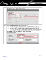
8.


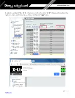
Select the last 52 port “

eth 1/0/52”

 in the menu on To Port, 

then enter “

12288

” in Maximum Frame Size on the 

right side of the Jumbo Frame window as below. And then click “

Apply

” button.


Содержание Enterprise AV KD-IP822DEC

Страница 1: ...genius Verified Switch Model List Engenius IGMP Setup for 1080p Systems Pg 43 Linksys Verified Switch Model List Linksys IGMP Setup for LGS MPC models Pg 47 Linksys IGMP Setup for 1080p Systems Legacy Pg 58 Linksys IGMP Setup for 4K Systems Legacy Pg 64 Luxul Verified Switch Model List Luxul IGMP Setup for 4K and 1080p Systems Pg 72 Netgear Verified Switch Model List Netgear AV Series Network Swit...

Страница 2: ...ent for 4K KD IP922 KD IP822 KD IP1022 and 1080p KD IP1080 KD IP120 systems There are separate setup instructions for each where applicable Key Digital AV over IP Supported Models 4K Systems o KD IP922ENC KD IP922DEC o KD IP822ENC KD IP822DEC o KD IP1022ENC KD IP1022DEC 1080p Systems o KD IP1080Tx KD IP1080Rx o KD IP120Tx KD IP120Rx KD IP120POETx KD IP120POERx Key Digital s AV over IP product fami...

Страница 3: ...40ms 4K Less at lower resolutions PoE Power Consumption 9 Watts per unit Required network cabling CAT6 UTP STP CAT6A CAT7 1080p Systems KD IP1080 KD IP120 models Video Compression Standard H 264 Data Stream Bandwidth 15 Mbps Stream Resolution Bandwidth 1080p 60Hz 15 Mbps 1080i 720p 60Hz 12 Mbps 480p 60Hz 4 Mbps Latency 400ms 1080p Less at lower resolutions PoE Power Consumption 6 Watts per unit Re...

Страница 4: ...he same series of network switch in these scenarios for best compatibility For 1080p systems KD IP1080 KDIP120 models that plan to use the video preview feature of the Key Digital App IGMP v3 must be enabled For 1080p or 4K systems that will not use the video preview feature IGMP v2 is enabled KD IP822 922 1022 systems require the following IP addresses to be reserved They cannot be assigned to KD...

Страница 5: ... POE 24 YES NO YES YES AN 210 SW F 24 POE 24 YES NO YES YES AN 210 SW F 48 POE 48 YES NO YES YES AN 310 SW R 8 8 NO NO YES YES AN 310 SW F 8 8 NO NO YES YES AN 310 SW R 16 16 NO NO YES YES AN 310 SW F 16 16 NO NO YES YES AN 310 SW R 24 24 NO NO YES YES AN 310 SW F 24 24 NO NO YES YES AN 310 SW R 8 POE 8 YES NO YES YES AN 310 SW F 8 POE 8 YES NO YES YES AN 310 SW R 16 POE 16 YES NO YES YES AN 310 S...

Страница 6: ...2 YES YES YES YES DGS 3630 28PC 28 YES YES YES YES YES DGS 3630 28SC 28 NO YES YES YES YES DGS 3630 28TC 28 NO YES YES YES YES DGS 3130 54PS 54 YES NO YES YES Edgecore Mellanox Edgecore AS4610 54T 48 YES YES YES YES Engenius EGS5212P 8 YES NO YES NO NO EGS7228FP 24 YES NO YES NO NO EGS7252FP 24 YES NO YES NO NO EWS1200D 10T 10 NO NO YES NO NO EWS1200D 28T 24 NO NO YES NO NO EWS1200D 52T 48 NO NO Y...

Страница 7: ... YES YES LGS318P 18 YES NO YES YES LGS326MP 26 YES NO YES YES LGS326P 26 YES NO YES YES LGS326 26 NO NO YES YES LGS318P 18 YES NO YES YES LGS318 18 NO NO YES YES LGS308MP 8 YES NO YES YES LGS308P 8 YES NO YES YES LGS308 8 NO NO YES YES Luxul AMX 4424P 24 YES YES YES YES Netgear GS716T 16 NO NO YES YES GS724T 24 NO NO YES YES GS748T 48 NO NO YES YES GS752TP 48 YES NO YES YES YES GS728TP 28 YES NO Y...

Страница 8: ...ed for KD IP1022 Niveo NGSME24TH AV 24 YES NO YES YES Pakedge S3L 24P 24 YES YES NO NO SX 8EP 8 YES YES SX 8P 8 YES YES YES SX 24 24 YES YES SX 24P8 24 YES 8 YES YES SX 24P16 24 YES 16 YES YES SX 24P 24 YES 24 YES YES Signamax SC30020 24 YES NO YES YES Titan Networx TNSS2400P 24 YES YES NO NO TP Link TL SG2428P 24 YES NO YES YES ...

Страница 9: ...conds and then release Wait while the device is restarted and ready to use about 5min 3 IMPORTANT At this point all the displays should be displaying distorted randomly flashing video images 4 Connect your PC to the Araknis network switch directly using a network cable 5 If you have not done yet configure your PC s IP address to the same range as the switch default 192 168 20 xxx 6 Enter the switc...

Страница 10: ...251 second to 192 168 1 252 and so on and each switch must be set individually same way as described below 9 Page will refresh Configure your PC s IP address to the same range as the switch default 192 168 1 xxx Enter the switch s IP address default is 192 168 1 251 in your browser and press ENTER 10 Make sure the settings remain as above 11 Navigate to Advanced Multicast IGMP Snooping Under Setti...

Страница 11: ...tart Switch After the reboot is complete check all settings again 14 IMPORTANT Now you can connect back you DHCP equipment routers servers and so on 15 Power down Araknis network switch and power it up back again Wait for the whole system to start and until you can see video on your displays 16 Log in to your Araknis network switch again and make sure that IGMP settings are intact 17 Rescan your c...

Страница 12: ...to the Araknis network switch directly using a network cable 5 If you have not done yet configure your PC s IP address to the same range as the switch default 192 168 20 xxx 6 Enter the switch s IP address default is 192 168 20 254 in your browser and press ENTER 7 Enter user name and password default is araknis for both Then click Log In 8 Navigate to Settings System Under IP Address Settings ele...

Страница 13: ...sure the settings remain as above 11 Navigate to Advanced Multicast IGMP Snooping Under Settings select Enable for Status V2 for Version and Enable for Report Suppression Under VLAN Settings VLAN ID 1 select Enable for IGMP Snooping Status and Enable for Fast Leave Under Querier Settings VLAN ID 1 select Enable for Querier State V2 for Querier Version and make sure all other setting are exactly as...

Страница 14: ...14 P a g e Back to top 12 Enter Settings Ports and set Jumbo Frame size to 9216 bytes enabling the required 8K jumbo frame support feature ...

Страница 15: ...ou can connect back you DHCP equipment routers servers and so on 16 Power down Araknis network switch and power it up back again Wait for the whole system to start and until you can see video on your displays 17 Log in to your Araknis network switch again and make sure that IGMP settings are intact 18 Rescan your components with Key Digital Management Software and make sure HDMI video switch is fu...

Страница 16: ...16 P a g e Back to top Cisco Meraki series After gaining access to the Cisco Dashboard navigate to the following and applied settings as depicted ...

Страница 17: ...re the green SYSTEM LED next to the pinhole RESET button is flashing 4 IMPORTANT At this point all the displays should be displaying distorted randomly flashing video images 5 Connect your PC to the Cisco network switch directly using a network cable 6 If you have not done yet configure your PC s IP address to the same range as the switch default 192 168 1 xxx 7 Enter the switch s IP address in yo...

Страница 18: ...18 P a g e Back to top 10 Getting Started screen will appear 11 Navigate to Configration Wizards to access the Gettting Started Wizard which will be used to set the desired IP address of the switch ...

Страница 19: ...19 P a g e Back to top ...

Страница 20: ...20 P a g e Back to top 12 Log in again using new password and new IP address 13 Navigate to Multicast IGMP Snooping Check the IGMP Snooping Status Enable box and click Apply ...

Страница 21: ...Snooping Status Check Enable box under Immediate Leave Check Enable box under IGMP Querier Status Select User Defined next to Administrative Querier Source IP Address and select 192 168 1 1 For IGMP Querier Version select IGMPV3 for IP1080 system If using IP922 system select IGMPV2 Then click Apply and Close Make sure all the setting are exactly as shown ...

Страница 22: ...rt Management section 16 On the top of the page click on flashing x Save For Source File Name select Running configuration For Destination File Name select Startup configuration Check the selections and make sure they are exactly as shown below Click Apply 17 Click Apply to confirm ...

Страница 23: ... the AV over IP equipment you should see image on your displays 20 Log in to your Cisco network switch again and make sure that IGMP settings are intact 21 Rescan your components with Key Digital Management Software and make sure HDMI video switch is functional 22 At this point your Linksys network switch is set and ready to use 23 Connect your encoders decoders allow approx 3 mins for bootup and ...

Страница 24: ...This action enables the switch to connect to local routers and the Internet You can access the switch through the IP address for further configuration Note Even you already finish Express Setup on your switch please check every step one by one Step 1 Make sure that nothing is connected to the switch Step 2 During Express Setup the switch acts as a DHCP server If your PC or laptop has a static IP a...

Страница 25: ...eller Step 6 Press and hold the Mode button until all the LEDs next to the Mode button turn green You might need to hold the button for more than 3 seconds The switch is now in Express Setup mode Troubleshooting If the LEDs next to the Mode button blink when you press the button release it Blinking LEDs mean that the switch is already configured and cannot go into Express Setup mode For more infor...

Страница 26: ... command line You will get Windows IP configuration and find IP address of Default Gateway Note According to Express Setup from Cisco it said 10 0 01 is default IP address But it s not correct for all Cisco Catalyst 3850 series It looks default IP address will be varied depend on Cisco Switches ...

Страница 27: ...nnect to 10 0 2 1 appear skip the User name and enter the default password cisco Troubleshooting If the Express Setup window does not appear make sure that any browser pop up blockers or proxy settings are disabled and that any wireless client is disabled on your PC or laptop Step 10 Click Continue button on Startup Report page Step 11 Select the Basic Settings on the Express Setup window and chan...

Страница 28: ...the command line interface CLI If you enable Telnet access you must enter a Telnet password In the Telnet Password field enter a password The Telnet password can be from 1 to 25 alphanumeric characters is case sensitive allows embedded spaces but does not allow spaces at the beginning or end In the Confirm Telnet Password field reenter the Telnet password And click Submit to save your changes and ...

Страница 29: ...ubnet of the Switch Step 14 To configuring Multicast IGMP Snooping and Jumbo Frame setting at the switch for KD IP922 devices you have to connect to the Switch via Telnet Note To access Telnet you can use PuTTY or Tera Term software We recommend to use Tera Term software and you can download it as below link https osdn net projects ttssh2 downloads 68252 teraterm 4 96 exe Run Tera Term software an...

Страница 30: ...net password once again Then Switch prompt will turn into Switch prompt as below Step 16 To Enable Jumbo Frame for IP922 Note IP922 requires Jumbo Frame 8K for video audio transmission via 1G BaseT with the Switch 16 1 Enter configure terminal on Switch prompt 16 2 Enter system mtu 9000 on Switch config prompt 16 3 Enter end on Switch config prompt 16 4 Enter copy running config startup config on ...

Страница 31: ...31 P a g e Back to top Step 17 To confirm Jumbo Frame setting on the switch 17 1 Enter show interfaces vlan 1 on Switch prompt You can check MTU 9000 bytes in the status of Vlan1 interface ...

Страница 32: ...nter ip igmp filter on Switch config prompt 18 5 Enter ip igmp snooping tcn query solicit on Switch config prompt 18 6 Enter ip igmp snooping querier on Switch config prompt 18 7 Enter ip igmp snooping querier version 2 on Switch config prompt 18 8 Enter ip igmp snooping vlan 1 immediate leave on Switch config prompt 18 9 Enter end on Switch config prompt 18 10 Enter copy running config startup co...

Страница 33: ...P a g e Back to top Step 19 To confirm multicast IGMP Snooping setting on the switch 19 1 Enter show ip igmp snooping detail on Switch prompt You can check global IGMP Snooping configuration on the switch ...

Страница 34: ...34 P a g e Back to top Connect your encoders decoders allow approx 3 mins for bootup and perform a network scan using KD Management Software ...

Страница 35: ...itch 1 Plug an Ethernet cable into any of the ports of the switch 2 Plug the other end into the Ethernet port of your computer 3 Power on the switch 4 Check to see that the IP address of the computer is within this network Subnet 10 90 90 xxx xxx ranges 1 254 For example 10 90 90 10 ...

Страница 36: ...indow appears as below 6 Leave the user name and password fields empty They are NOT required Click Login to login to the switch configuration window Enable Jumbo Frame 7 Find System Port Configuration Jumbo Frame in the menu on left side of the window IP922 requires Jumbo Frame 8K for video audio transmission via 1G BaseT ...

Страница 37: ...37 P a g e Back to top 8 Select the last 52 port eth 1 0 52 in the menu on To Port then enter 12288 in Maximum Frame Size on the right side of the Jumbo Frame window as below And then click Apply button ...

Страница 38: ... of the window KD IP922 requires IGMP Snooping for multicasting video audio transmission via 1G BaseT Check the Global State Enabled box of Global Settings in IGMP Snooping Settings window as below Click Apply button on the right side of IGMP Snooping Settings window 11 To add VLAN of the IGMP Snooping at the switch enter 1 in VID of VLAN Status Settings VLAN must be added in IGMP Snooping Then se...

Страница 39: ...ttings window 13 In the IGMP Snooping VLAN Settings window select below options as depicted below in red and then click Apply button Minimum Version 2 Fast Leave Enabled Report Suppression Enabled Querier State Enabled Query Version 2 Ignore Topology Change Enabled ...

Страница 40: ...work switches connecting multiple network switches through D Link 10G fiber cables it is recommended to set first on to 10 90 90 91 second to 10 90 90 92 and so on Set Get IP From Static set Subnet Mask to 255 0 0 0 and click Apply If you change an IP address the page will be refreshed and you will need to log in again using new IP address same user name and password If you did not change IP addre...

Страница 41: ...ve Configuration in the menu on top of the window Then click Apply button in Save Running Configuration to startup config window 16 To reboot the switch Find Tool Reboot System in the menu on top of the window Then click Reboot button in Reboot System window The switch will be rebooted automatically ...

Страница 42: ... enabled no net add ptp global use syslog yes net add ptp global verbose no net add ptp global summary interval 0 net add ptp global time stamping net add bridge bridge mld version 2 net add bridge bridge ports swp1 swp2 swp3 swp4 swp5 swp6 swp7 swp8 swp9 swp10 swp11 swp12 swp13 swp14 swp15 swp16 swp17 swp18 swp19 swp20 swp21 s wp22 swp23 swp24 swp25 swp26 swp27 swp28 swp29 swp30 swp31 swp32 swp33...

Страница 43: ...n for more than 10 seconds and then release After device is rebooted power down and then power up the device Wait while the device is restarted and ready to use 2 Connect your PC to the switch directly using a network cable 3 Configure your PC s IP address to the same range as the switch default 192 168 0 xxx 4 Enter the switch s IP address default is 192 168 0 239 in your browser and press ENTER ...

Страница 44: ...92 168 1 250 Subnet Mask to 255 255 255 0 Default Gateway to 192 168 1 1 in this case and at the bottom click Apply 7 Page will refresh Configure your PC s IP address to the same range as the switch default 192 168 1 xxx Enter the switch s IP address default is 192 168 1 250 in your browser and press ENTER Log in again with the same user name password ...

Страница 45: ...45 P a g e Back to top 8 On the left select Switch Navigate to L2 Feature IGMP Snooping Global Settings Under Status select Enabled under Version V2 and under Report Suppression Enabled Click Apply ...

Страница 46: ...LAN ID 1 line Under IGMP Snooping Status select Enabled under Fast Leave select Enabled Click check mark button to apply settings 10 Now the switch should work properly with IP audio video equipment 11 Connect your encoders decoders allow approx 3 mins for bootup and perform a network scan using KD Management Software ...

Страница 47: ...etwork switch 192 168 1 xyz 2 Connect to the network switch via its default IP address 192 168 1 251 The default login credentials are Username admin Password admin After connecting change the password to gain access to the switch 3 Set the IP address of the switch to the desired address This setting is accessed via System IP settings IPv4 Management 3a If stacking multiple network switches each w...

Страница 48: ... Multicast IP Config IGMP Snooping Ensure all settings are in line with the image 5 Enable IGMP snooping for your VLAN This setting is accessed via Configure Multicast IP Config IGMP Snooping VLAN Settings Use IGMP version 2 VLAN 1 is used by default Other VLANs are compatible as well ...

Страница 49: ...ble Fast leave for all ports This setting is accessed via Configure Multicast IP Config IGMP Snooping Port Settings 7 Enable the IGMP querier This setting is accessed via Configure Multicast IP Config IGMP Snooping Querier Settings ...

Страница 50: ...50 P a g e Back to top 7a Select one switch to be the IGMP querier Enable the querier on this switch only and disable the IGMP querier on all other switches ...

Страница 51: ...51 P a g e Back to top 8 Set the frame size to its maximum value of 10240 Configure Port Settings Jumbo Frames ...

Страница 52: ...nfigure Port Settings Multicast Filtering 10 Verify all settings are applied after power cycling The switch should now be ready to use 11 Connect your encoders decoders allow approx 3 mins for bootup and perform a network scan using KD Management Software ...

Страница 53: ... than 10G Link Aggregation may be required To enable link aggregation navigate to Configure Link Aggregation A single SFP port on the switch can carry a maximum of 10G bandwidth Each additional SFP port added to the group will add an additional 10G of bandwidth for up to a maximum of 40G ...

Страница 54: ...ork switch 192 168 1 xyz 14 Connect to the network switch via its default IP address 192 168 1 251 The default login credentials are Username admin Password admin After connecting change the password to gain access to the switch 15 Set the IP address of the switch to the desired address This setting is accessed via System IP settings IPv4 Management 3a If stacking multiple network switches each wi...

Страница 55: ...g is accessed via L2 feature IGMP Snooping VLAN settings Use IGMP version 2 VLAN 1 is used by default Other VLANs are compatible as well 5a Ensure Fast Leave is disabled when stacking 18 Enable the IGMP querier This setting is accessed via L2 feature IGMP Snooping Querier settings 6a Select one switch to be the IGMP querier Enable the querier on this switch only and disable the IGMP querier on all...

Страница 56: ...56 P a g e Back to top 19 Set the frame size to its maximum value of 10240 L2 feature Jumbo Frame ...

Страница 57: ...ring L2 feature Multicast Filtering 21 Verify all settings are applied after power cycling The switch should now be ready to use 22 Connect your encoders decoders allow approx 3 mins for bootup and perform a network scan using KD Management Software ...

Страница 58: ...ble 6 If you have not done yet configure your PC s IP address to the same range as the switch default 192 168 1 xxx 7 Enter the switch s IP address in your browser and press ENTER check the user manual for a default IP address it is usually 192 168 1 251 8 Enter user name and password check the user manual for a default user name and password it is usually admin for both Then click Log In 9 Naviga...

Страница 59: ...dress page will refresh and you will need to log in again using new IP address same user name and password If you did not change IP address just continue to the next step 10 Make sure your screen looks exactly like pictured below ...

Страница 60: ...e Back to top 11 Navigate to Multicast Future Configuration Select Enable under Bridge Multicasting Filtering and click Apply 12 Navigate to Multicast IGMP Snooping Select Enable under IGMP Snooping click Apply ...

Страница 61: ... Edit IGMP Snooping window will appear Make sure VLAN ID 1 is selected Enable all the settings as shown below Select IGMP v3 as IGMP Querier Version Click Apply and then Close 14 Refresh your browser go to IGMP Snooping tab and make sure you have an image as below ...

Страница 62: ...te to Maintenance File Management Configuration File Copy Select radio buttons as shown below click Apply This will save current configuration and will apply this configuration every time switch is powered up 17 IMPORTANT Now you can connect back you DHCP equipment routers servers and so on 18 Power down Linksys network switch and power it up back again Wait for the whole system to start and until...

Страница 63: ...e intact 20 Rescan your components with Key Digital Management Software and make sure HDMI video switch is functional 21 At this point your Linksys network switch is set and ready to use 22 Connect your encoders decoders allow approx 3 mins for bootup and perform a network scan using KD Management Software ...

Страница 64: ...etwork cable 6 If you have not done yet configure your PC s IP address to the same range as the switch default 192 168 1 xxx 7 Enter the switch s IP address in your browser and press ENTER check the user manual for a default IP address it is usually 192 168 1 251 8 Enter user name and password check the user manual for a default user name and password it is usually admin for both Then click Log In...

Страница 65: ...will refresh and you will need to log in again using new IP address same user name and password 10 Make sure your screen looks exactly like pictured below 11 Navigate to Port Management Ports Select Enable under Jumbo Frames and click Apply ...

Страница 66: ...66 P a g e Back to top 12 Navigate to Multicast Future Configuration Select Enable under Bridge Multicasting Filtering and click Apply ...

Страница 67: ...67 P a g e Back to top 13 Navigate to Multicast IGMP Snooping Select Enable under IGMP Snooping click Apply ...

Страница 68: ... top 14 Click on radio button and click Edit Edit IGMP Snooping window will appear Make sure VLAN ID 1 is selected Enable all the settings as shown below Select IGMP v2 as IGMP Querier Version Click Apply and then Close ...

Страница 69: ...69 P a g e Back to top 15 Refresh your browser go to IGMP Snooping tab and make sure you have an image as below ...

Страница 70: ...radio buttons as shown below click Apply This will save current configuration and will apply this configuration every time switch is powered up 17 Power down Linksys network switch and power it up back again 18 Log in to your Linksys network switch again and make sure that IGMP settings are intact ...

Страница 71: ...a g e Back to top 19 At this point your Linksys network switch is set and ready to use 20 Connect your encoders decoders allow approx 3 mins for bootup and perform a network scan using KD Management Software ...

Страница 72: ... stacking 1 Login to the switch a Plug an Ethernet cable into any of the ports of the switch b Plug the other end into the Ethernet port of your computer c Power on the Switch d Check to see that the IP address of the computer is within this network Subnet 192 168 0 xxx xxx ranges 1 254 For example 192 168 0 100 2 Open the Web browser and enter 192 168 0 4 default IP address of Luxul AMS 4424P The...

Страница 73: ...check it find Configuration Ports Ports in the menu on left side of the window KD IP922 requires Jumbo Frame 8K for video audio transmission via 1G BaseT 5 To enable IGMP Snooping of the switch Find Configuration IPMC IGMP Snooping Basic Configuration in the menu on left side of the window KD IP922 requires IGMP Snooping for multicasting video audio transmission via 1G BaseT then check the box of ...

Страница 74: ...lick Save button on the bottom of IGMP Snooping Configuration window 7 To add VLAN of the IGMP Snooping at the switch Find Configuration IPMC IGMP Snooping VLAN Configuration in the menu on left side of the window VLAN must be added in IGMP Snooping then click Add New IGMP VLAN if there is not any specified VLAN in IGMP Snooping VLAN Configuration window ...

Страница 75: ...D check the box of Snooping Enabled and Querier Election in new VLAN And select Forced IGMPv2 in the list box of Compatibility in IGMP Snooping VLAN Configuration window Then click Save button on the bottom of IGMP Snooping VLAN Configuration window ...

Страница 76: ...urations to Startup Configuration Find Administration Configuration Save startup config in the menu on left side of the window Then click Save Configuration button in Save Running Configuration to startup config window 11 To reboot the switch Find Administration Reboot in the menu on left side of the window Then click Yes button in Reboot Device window The switch will be rebooted automatically ...

Страница 77: ...77 P a g e Back to top ...

Страница 78: ...s compatible with IP822 IP922 and IP1022 with no additional configuration required However for ease of maintenance it is recommended to adjust the IP address of the switch to match the subnet of the IP system If creating a new profile for an AV specific VLAN use the Video preset for the best performance ...

Страница 79: ...cable into any of the ports of the switch 2 Plug the other end into the Ethernet port of your computer 3 Power on the Switch 4 Check to see that the IP address of the computer is within this network 192 168 0 xxx xxx ranges 1 254 For example 192 168 0 100 5 Open the Web browser and enter 192 168 0 239 default IP address of Netgear GS The login window appears as below ...

Страница 80: ...e of the switch go to Switching Ports Port Configuration IP922 requires Jumbo Frame 8K for video audio transmission via 1G BaseT Select the empty checkbox that is above the checkbox beside g1 Port in the table to select all the ports All selected ports highlight to yellow color Then enter 9216 in Maximum Frame Size field as shown below and press Apply button ...

Страница 81: ...nsmission via 1G BaseT Enable IGMP settings as shown below and press Apply button 10 Go to Switching Multicast IGMP Snooping IGMP Snooping Interface Configuration Select the empty checkbox that is above the checkbox beside g1 Port in the table to select all the ports All selected ports highlight to yellow color Enable Admin Mode and Fast Leave Admin Mode as shown below and press Apply button ...

Страница 82: ...d VLAN ID 1 Fast Leave Admin Mode Enable and Query Mode Enable as shown below and press Add button Note the empty fields are populated automatically to default values 12 Go to Switching Multicast IGMP Snooping Querier Querier Configuration Enable Querier Admin Mode as shown below and press Apply button ...

Страница 83: ...Finally go to Maintenance Device Reboot Enable checkbox for device reboot as shown below and press Apply button It takes approximately 2 minutes to power cycle the switch and an additional 2 min for IP922 to start showing video ...

Страница 84: ... to the switch The best method is to set a static IP address for the computer s ethernet adapter and directly wire into the switch The Default IP address of this switch is 192 168 2 1 2 Once wired in connect to the network switch via web browser When prompted log in with the default credentials a The username and password are both admin ...

Страница 85: ...ter connecting to the switch it is recommended to reset it to factory defaults a The path for this is Maintenance Factory Defaults b Note that resetting the switch to Factory Defaults does not change the IP settings of the switch ...

Страница 86: ... the router in the network a The path is Configuration System IP b After making the adjustment the switch will automatically move to the new IP address The computer may lose connection to the switch at this time Adjusting the static IP to be in the new subnet will allow for connection to be reestablished on the new IP address 5 By default Jumbo frames are enabled on this network switch Verify that...

Страница 87: ...Create an IGMP VLAN The ID should be set to 1 Force IGMPV2 compatibility for this VLAN Ensure the configuration is as below a The path is Configuration IPMC IGMP VLAN Configuration 8 Reboot the network switch and verify that the settings are correct The switch is now ready for the KD IP922 system a There is no need to save the running configuration of this network switch The settings will persist ...

Страница 88: ...he switch with the following steps 1 Plug an Ethernet cable into any of the ports of the switch 2 Plug the other end into the Ethernet port of your computer 3 Power on the Switch 4 Check to see that the IP address of the computer is within this network 192 168 1 xxx xxx ranges 1 254 For example 192 168 1 154 ...

Страница 89: ...window appears as below 6 Enter the User ID default user id is pakedge and password default password is pakedges And then click OK to login to the switch configuration window Make sure to set appropriate IP address and netmask to make the switch to be in same network as the Key Digital Devices you are going to be using ...

Страница 90: ...t Port IP922 requires Jumbo Frame 8K for video audio transmission via 1G BaseT Make sure under Port Settings Port field is set to All Then enter 9216 in Maximum Receive Frame Size field as shown below and press Apply button After applying check that the settings are updated in the table below ...

Страница 91: ...ng of the switch go to Configure Application IGMP Snooping IP922 requires IGMP Snooping for multicasting video audio transmission via 1G BaseT Enable IGMP settings as shown below and press Apply button You should see a new entry in the table below ...

Страница 92: ...92 P a g e Back to top 9 Go to Configure Application IGMP Enter the settings as shown in the picture below and press Apply button You should see the updated settings in the entries table below ...

Страница 93: ... top 10 Go to Maintenance Save Click on Save button 11 Go to Maintenance Reboot Click on Reboot button It takes approximately 30 seconds for the switch to reboot and an additional 30 sec for IP922 to start showing video ...

Страница 94: ...her end into the Ethernet port of your computer c Power on the Switch d Configure the PC with static IP address of 192 168 1 10 and the subnet mask of 255 255 255 0 to be within range of Pakedge s default settings IP address 192 168 1 205 subnet mask 255 255 255 0 Default Getaway and DNS can be left blank 2 Open a web browser and enter 192 168 1 205 default IP address of Pakedge to enter the login...

Страница 95: ...he user name and password default user name is pakedge and password is pakedges and then click Login to login to the switch configuration window 4 Go to System Settings and change the Subnet Mask to 255 255 0 0 Press the apply button ...

Страница 96: ...ack to top 5 Go to Port Port Settings MTU and change MTY to 10 000 max 6 Go to TRAFIC IGMP IGMP Snooping and Enable IGMP Status and Report Suppression Press the Apply button 7 Press the button with red pencil icon ...

Страница 97: ...97 P a g e Back to top 8 Enable State and Immediate Leave 9 Go to TRAFIC IPMC IGMP Querier and press the button with red pencil icon 10 Enable State and choose IGMPv2 version Click Apply button ...

Страница 98: ...98 P a g e Back to top 10 Go to TRAFIC IPMC MULTICAST PORPERTY and set Unknown Multicast Action to Drop Press Apply ...

Страница 99: ...Your PC will need to be set to a static IP address that is within the subnet of the default IP address of the switch This series of switches typically use 192 168 2 1 as their default IP address 2 Log into the switch via web browser using the IP address There will be a prompt to enter credentials By default both username and password are set to admin ...

Страница 100: ...ate to System Capability and enable Jumbo Frames as depicted in the below image 4 Navigate to Multicast IGMP Snooping General to access basic IGMP settings On this page enable IGMP snooping and Querier as depicted in the below image ...

Страница 101: ...101 P a g e Back to top 5 Navigate to Multicast IGMP Snooping Interface From this page use the dropdown to select Configure VLAN Set VLAN 1 up as depicted below ...

Страница 102: ...6 Navigate to IP General Routing Interface From this page use the dropdown to select Add address Add a new static primary IP address for VLAN 1 from this screen For best performance use an IP in the same subnet as your system ...

Страница 103: ...103 P a g e Back to top 7 To save all settings click on the floppy disk button on the top right corner of the control panel then reboot After rebooting the switch will be ready to manage an IP system ...

Страница 104: ... range as the switch default 192 168 1 xxx 6 Enter the switch s IP address in your browser and press ENTER check the user manual for a default IP address usually it is 192 168 1 30 7 Enter user name and password check the user manual for a default user name and password it is usually admin for both Then click Log In 8 Navigate to Administration System Configuration Select IP Address box IP address...

Страница 105: ... e Back to top 9 Make sure your screen looks exactly like pictured below 10 Click Save Configurations on the left bottom corner New screen will appear Click Save under Save Current Settings then OK and OK again ...

Страница 106: ...evice Management IGSP Select IGMP Snooping tab Set IGSP Status to Enable set Unknown Multicast Drop to Enable set Multicast VLAN Status to Enable set Multicast VLAN ID to 1 and leave all other settings as indicated below Click OK and OK again ...

Страница 107: ...107 P a g e Back to top 12 Select Fast Leave tab Click Config button 13 Set Fast Leave to Enable click Select All Click OK and OK again ...

Страница 108: ...the left bottom corner New screen will appear Click Save under Save Current Settings than OK and OK again 16 Power down Titan Networx network switch and power it up back again Wait for the switch to reboot 17 Log in to your Titan Networx network switch again and make sure that IGMP settings are intact ...

Страница 109: ...109 P a g e Back to top ...

Страница 110: ... e Back to top 18 At this point your Titan Networx network switch is set and ready to use 19 Connect your encoders decoders allow approx 3 mins for bootup and perform a network scan using KD Management Software ...

Страница 111: ...g a paper clip press and hold a reset button for more than 5 seconds and then release The factory reset process generally takes 5 minutes to complete 4 Connect your PC to the TP Link network switch directly using a network cable 5 If you have not done yet configure your PC s IP address to the same range as the switch default subnet of the switch 192 168 0 xxx 6 Enter the switch s IP address in you...

Страница 112: ... of the network switch 9 Select Static and enter the desired IP address and subnet mask Click Apply IP address can be changed by the administrator depending on the network configuration We recommend using an address that is within the subnet of the AVoIP system for ease of maintenance After applying you will need to log in again using new IP address Ensure the PC and switch are the same network be...

Страница 113: ...113 P a g e Back to top 10 Confirm the updated IP address table Go to L3 FEATURES IPv4 Routing Table 11 Enable Jumbo Frames Go to L2 Features Port and set frame size to 9216 ...

Страница 114: ...2 FEATURES Multicast MLD Snooping Select Enable under MLD Snooping Click Apply 13 Go to L2 FEATURES Multicast IGMP Snooping Global Config Select Enable under IGMP Snooping Select v2 version and Discard for Unknown Multicast Groups And click Apply ...

Страница 115: ...ettings from the step 13 click the icon under IGMP VLAN Config table 15 IGMP Snooping window will appear Make sure below settings red boxes enabled Change General Query Source IP to the current network switch s IP address 192 168 1 251 in this case ...

Страница 116: ...116 P a g e Back to top 16 Scroll down the window and leave all the ports unchecked Click Save ...

Страница 117: ...k to top 17 Enable Fast Leave on all ports Go to L2 FEATURES Multicast IGMP Snooping Port Config 18 View IGMP VLAN Configurations Go to L2 FEATURES Multicast IGMP Snooping Global Config Click icon yellow box in image ...

Страница 118: ...up 20 To double check the updated configuration reboot the network switch and confirm the configuration After rebooting the switch log in to your TP Link network switch again and make sure that IGMP settings are intact 21 At this point your Linksys network switch is set and ready to use 22 Connect your encoders decoders allow approx 3 mins for bootup and perform a network scan using KD Management ...

Страница 119: ...the Key Digital app 1080p systems KD IP1080 KD IP120 only Verified model Cisco Linksys EA6700 router Network switch must support IGMP v3 and configured to enable IGMP v3 Wifi Router Must be configured so that multicast filtering is enabled See above example Must support 50Mbps bandwidth per iOS that will be streaming video It is recommended that only 1 iOS be in the Live Stream page at a time iOS ...

Отзывы: