background image

31

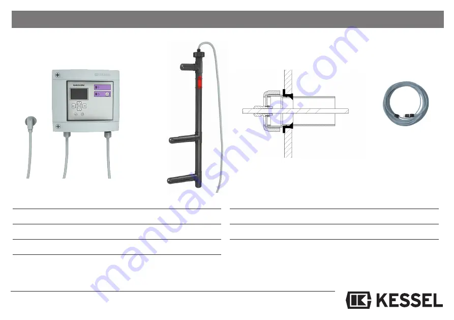
10. Ersatzteile und Zubehör

                                                                                     Best.-Nr.

1

1.    Schaltgerät                                                          680349

1

2.    Ultraschallsensor (bis 09/2011)                           917821

2.    Ultraschallsensor (ab 10/2011)                            680348

3.    Durchführungsset für Erdeinbau                         917822

1

                                                                                     ^

                                                                                     Best.-Nr.

4.      Kabelverlängerung 10 m                                     917871

4.      Kabelverlängerung 20 m                                     917872

4.      Kabelverlängerung 30 m                                     917873

innen

außen

Содержание 917824

Страница 1: ...sertemperatur im Abscheider Batteriegepufferter Alarm bei Stromausfall Einfache Montage inkl Montageset Schutzart Ultraschallsonde IP 68 Produktvorteile Name Unterschrift Datum Ort Stempel Fachbetrieb Installation der Anlage wurde durchgeführt von Ihrem Fachbetrieb Inbetriebnahme Einweisung Änderungsstand 10 2016 Sachnummer 395 016 Techn Änderungen vorbehalten Abbildung zeigt Art Nr 917821 D Seite...

Страница 2: ...t Seite 15 4 4 Installation Kabelanschluss Seite 16 4 5 Anschlussplan Seite 19 5 Inbetriebnahme 5 1 Betriebsbereitschaft Seite 20 5 2 Pflichten des Betreibers Seite 20 5 3 Einweisung Übergabe Seite 20 6 Inspektion und Wartung Seite 21 7 Ereignisse Fehler und Abstellmaßnahmen 7 1 Ereignisanzeige Seite 22 7 2 Fehleranzeige Seite 23 7 3 Allgemeine Fehler Seite 24 7 4 Anlagenfehler Seite 25 8 Schaltge...

Страница 3: ...8 8 4 3 Wartungstermin Seite 28 8 4 4 Entsorgungstermin Seite 28 8 5 Einstellungsmenü Seite 29 8 5 1 Parameter Seite 29 8 5 2 Profilspeicher Seite 29 8 5 3 Datum Uhrzeit Seite 29 8 5 4 Anlagenart Seite 29 8 5 5 Typ Fettabscheider Seite 29 8 5 6 Sprache Seite 29 8 5 7 Kommunikation Seite 29 8 5 8 Sensoren Seite 29 8 5 9 Zurücksetzen Seite 29 9 Technische Daten Seite 30 10 Ersatzteile und Zubehör Se...

Страница 4: ... müssen den Bestimmungen Angaben der örtlichen Energie Versorgungsunter nehmen EVU entsprechen Die Anlage darf nicht in explosions gefährdeten Bereichen betrie ben werden Die Anlage enthält elektrische Spannungen Bei Nichtbeachtung der Bedienungsanleitung können erheblicher Sachschaden Kör perverletzung oder gar tödliche Unfälle die Folge sein Vor allen Arbeiten an der Anlage ist diese sicher vom ...

Страница 5: ... der Spitze zum Ruhewasserspiegel Ruhewasserspiegel Unterkante Ablauf ist das Niveau des Ruhewasserspiegels Ausrichtungshilfe Mit der Ausrichtungshilfe schwarze Endkappe oberhalb der Fettschicht sehen Sie in welche Richtung die unteren Sensorfinger zeigen Fett Das Messgerät ist für Fette und Öle mit einer Dichte von 0 85 g cm3 voreingestellt Die voreingestellte Dichte entspricht mit 0 85 g cm3 dem...

Страница 6: ...d von 168 mm Standard an bringen Die 2 Linsenkopfschrauben 4 5 x 35 mm TX20 soweit eindrehen dass das Schalt gerät wandbündig eingehängt werden kann Hierbei auf genügend Wandabstand rechts achten damit eine Deckelöffnung möglich ist Die Schrauben die Kunststoffdübel und eine Bohrschablone sind im Lieferumfang enthalten Montage 1 Bohren der Löcher 2 Einschieben der Dübel in die Bohrlöcher 3 Schraub...

Страница 7: ...uf Sensor Halter befestigen Sensor Halter am Auslaufbauwerk mit 1 Nm festschrauben und Sensor einklipsen Bei den unteren beiden Rohrschellen die Klammern anclipsen oben die Klammern weglassen Sensor Halter 6 Kantschraube SW 10 8 x 40 Senkkopfschraube AW 20 5 x 30 Rohrschelle PP D32 Bohrschablone Schraubenabdeckung Auslaufbauwerk Trennwand Sensor SonicControl Markierung roter Pfeil Für Fettabscheid...

Страница 8: ...14 11 22 93003 01 02 11 12 21 22 31 32 3 50 cm 17 14 29 93004 01 02 11 12 21 22 31 32 4 50 cm 17 14 30 93007 01 02 11 12 21 22 31 32 7 50 cm 21 17 35 93010 01 02 11 12 21 22 31 32 10 50 cm 21 17 38 98201 Obere beiden Bohrlöcher der Bohrschablone verwenden 1 58 cm 16 13 46 98202 Obere beiden Bohrlöcher der Bohrschablone verwenden 2 58 cm 16 13 54 D 93002 01 D 02 D 11 D 12 D 21 D 22 D 31 D 32 D 2 50...

Страница 9: ...0 cm 21 17 35 93010 01 DS 02 DS 31 DS 32 DS 10 50 cm 21 17 38 DSP 93002 01 DSP 02 DSP 2 50 cm 14 11 22 93003 01 DSP 02 DSP 3 50 cm 17 14 29 93004 01 DSP 02 DSP 4 50 cm 17 14 30 93007 01 DSP 02 DSP 7 50 cm 21 17 35 93010 01 DSP 02 DSP 10 50 cm 21 17 38 MS 93002 01 MS 02 MS 2 50 cm 14 11 22 93003 01 MS 02 MS 3 50 cm 17 14 29 93004 01 MS 02 MS 4 50 cm 17 14 30 93007 01 MS 02 MS 7 50 cm 21 17 35 93010...

Страница 10: ...einbau Artikelnummer NS Abstand Oberkante unterer Finger zu Unterkante Auslauf Wasserlinie Alarmschichtdicke in cm Voralarmschichtdicke in cm bei 80 max Schlammschicht dicke in cm 50 des Schlammfangvolumen Euro G 93002 80 120 B und D 2 50 cm 17 14 15 93004 80 120 B und D 4 50 cm 17 14 27 93007 120 170 B und D 7 48 cm 17 14 23 93010 120 170 B und D 10 48 cm 17 14 23 93015 120 170 B und D 15 56 cm 1...

Страница 11: ...hlag Abb zeigt Fettabscheider EasyClean NS4 Kabeldurchführung für SonicControl frei aufgestellte Fettabscheider Fettabscheider Kabel Gewinde PG 11 Kabelverschraubung Behälterwand um Geruchsbelästigungen zu vermei den Kableverschraubung dicht anziehen ...

Страница 12: ...12 3 Einbau und Montage Das Kabel darf nicht im Bereich über dem Sensor liegen Abbildung zeigt Draufsicht Sensor an EasyClean Bauwerk anschlagen 30 cm freier Umfang um den Sensorfinger ...

Страница 13: ...ber 45 sind zu vermeiden Das Kabelleerrohr sollte ein stetiges Ge fälle zum Abscheider aufweisen Kondenswasserbil dung innerhalb des Kabelleerohres kann durch einen luftdichten Abschluss des Leerrohres auf Seite des Schaltgeräts minimiert werden Für eventuelle nachträg liche Kabelverlegungen kann ein Kabeldurchzugsdraht mit eingelegt werden Die Verlängerung des Kabels ist auf max 60 m möglich Beim...

Страница 14: ...igen Sie hierzu das Rohr D in den Halteclips C und befestigen Sie den SonicControl Sensor durch die mitgelie ferten 8 er Clips E 5 Clipsen Sie den Sensor in die Halte clips C der Montagehalterung B und befestigen Sie die Montagehalterung an den 2 Schrauben Drehen Sie dann die Schrauben fest dass die Montagehalte rung fest sitzt 6 Justieren Sie nun SonicControl an der roten Markierung am Sensor mit...

Страница 15: ...ngen Die Sensorleitungen können bei Bedarf auch gekürzt werden Wir empfehlen an den Aderenden dann nur noch die Spitzen zu ver zinnen Bei der Verwendung von Aderendhülsen ist zu beachten dass die Anschlußklemmen für einen max Querschnitt von 2 5 mm2 ausgelegt sind Dieser Querschnitt darf nicht überschritten werden 4 3 Potentialfreier Kontakt Befestigen Sie den potentialfreien Kontakt an den Anschl...

Страница 16: ...arm funktion beeinträchtigen Der Sensor selbst darf nicht geerdet wer den WICHTIG Alle an dem elektrischen Schaltgerät angeschlossenen Kabel sind bei beendeter Installation durch geeignete Maßnahmen z B Kabel binder so zu fixieren daß sie im 1 Fehler Fall also beim Lösen einer Verbindung nicht zu einer Gefährdung führen Die Sensorleitung ist getrennt von der Netzleitung zu verlegen um Störeinflüss...

Страница 17: ... zu be achten Das Schaltgerät darf nicht in ex plosionsgefährdeten Räumen installiert werden Das 10 m Kabel ist bauseits auf bis zu 60 m Kabellänge verlängerbar Wenn das Kabel in einem Kabelkanal mit Kabeln an derer frequenzgeregelter Geräte verlegt wird ist ein geschirmtes Kabel zu verwen den Abb 1 Kabelverlängerung mit Stoßverbinder ver quetschen Abb 2 Schale wird um die Leitung gelegt Scha lene...

Страница 18: ...chaft Kontrolllampe für Störungsmeldung Alarmtaste Bewegungstasten Richtungstasten für die Führung durch das Programm Menü Zurücktaste ESC Taste Display Anzeigenfeld Netzanschlusskabel USB Slot Anschlussmöglichkeiten für externen Signalgeber potentialfreien Kontakt Modemanschluss Anschluss Sensor SonicControl ...

Страница 19: ... or or bl bl sw ws bl or or or or SHD 1 P P B A PC 14 12 11 PE N MODEM GND or or or bl gn sw GND RG Rx RS Tx SENSOR POTENTIALFREIER KONTAKT switch contact max 42V 0 5A L1 ANSCHLUSS FERNBEDIENUNG 12 11 14 3 3 3 ws br ws gn sw bl optional 916601 3 2 2 FERNSIGNAL GEBER bl or ...

Страница 20: ...ngsan leitung EBA EBA mit Kunde durchgehen Bedienung der Anlage erklären und beschreiben Aufklären des Kunden über die Pflichten des Betreibers auf regelmässige Wartung siehe Kapitel 6 hinweisen 5 3 Einweisung Übergabe Das Kapitel Sicherheitshinweise ist zu beachten Seite 4 Die Inbetriebnahme wird von einem Fachbetrieb oder einem KES SEL Beauftragten durchgeführt gegen Aufpreis Folgende Per sonen ...

Страница 21: ... gereinigt werden Bei Verwendung eines Hochdruck reinigers 30 cm Sicherheitsabstand einhalten Der Sensor muss zur Reinigung nicht entnommen werden Der Abscheider ist nach der Entleerung mit Wasser zu befüllen Bei KESSEL D SP MS und PVS Fettabscheider Anlagen kann auf die Reinigung des Sensors bis zur nächsten Wartung verzich tet werden da der Abscheider mit warmem Wasser gereinigt wird Bei Bedarf ...

Страница 22: ...nart geändert Art der Anlage wurde geändert Wartung Wartungstermin wurde eingetragen Handbetrieb Handbetrieb wurde eingetragen Logbuch auslesen Logbuch wurde ausgelesen Schaltgerät runterfahren Schaltgerät wurde runter gefahren Akustischer Alarm quittieren Akustischer Alarm wurde quittiert Fehler quittieren Fehler wurde quittiert Werkseinstellungen Zurückgesetzt auf Werkseinstellungen Kalibrierung...

Страница 23: ...Blinken Alarm Maximale Fettschichtdicke Entsorger verständigen erreicht siehe auch 3 3 ALARM Temperatur Warnton und Blinken Alarm Zulauftemperatur zu hoch Temperatur Zulaufwasser zur Einstellung des Niveaus verringern normative Vorgaben be achten Warnton und Blinken Alarm Kontaktfehler an der Batterie auf Polarität und Sitz Batteriefehler Batterie prüfen Warnton und Blinken Alarm Batterie defekt o...

Страница 24: ...annter Fehler Fehler Ursache Abstellmaßnahme Abweichung zwischen Fehlfunktion durch mangelhafte Montage Kabel locker anziehen und Fettschichthöhe im Schau Fehlmessung des Sensors anschließend Verschraubung glas und gemessener handfest anziehen Fettschichthöhe Positionierung beim Art des Abscheiders Einbau berücksichtigen mang Erstinitialisierung Neukalibrierung des Sensors Schmutzablagerungen Über...

Страница 25: ...ein Modem Einsatz möglich wenn Empfang besteht dann Austausch des Modems 7 4 Anlagenfehler Erkannter Fehler Ursache Abstellmaßnahme Geruchsbelästigung Undichtheit der Kabeldurchführung durch Kabelverschraubung in der Behälter Fehlverbau wand geruchsdicht anziehen siehe auch Bedienungsanleitung Ihres Fettabscheiders Wasser im Betriebsraum Undichtheit der Kabeldurchführung Kabelverschraubung in der ...

Страница 26: ...by Modus Batterie Betrieb Dies macht sich durch einen akustischen und optischen Alarm bemerkbar Durch Betätigen der Alarmtaste kann der akusti sche Alarm quittiert werden Der Stand by Modus wird für mind 72 Stunden aufrecht erhalten Anschließend schaltet sich das Schaltgerät selbständig aus Wird während einer Stunde der Netzanschluss wiederhergestellt fährt das Programm selbständig mit der letzten...

Страница 27: ...führten Wartung Hinweis Daten liegen nur vor wenn diese vom Wartungspartner im Menü Einstel lungen hinterlegt worden sind 8 3 5 Aktuelle Messwerte Durch Betätigen der OK Taste wird eine Messung der aktuellen Fettschichtdicke durchgeführt 8 3 6 Parameter Anzeige aller eingestellten Steuerungsparameter der Anlage Eine Änderung der Parameter ist in diesem Menü nicht möglich 8 3 7 Messdatenspeicher An...

Страница 28: ...nd die Messergebnisse verfälscht Im Abscheider sind zu viele Schwebstoffe welche die Messung beeinflussen 8 4 2 Wartungstermin Eingabe der zuletzt durchgeführten Wartung und des nächsten Wartungster mins durch den Wartungspartner Passwort 1000 8 4 3 Wartung durchgeführt Datenspeicherung Bestätigung von durchgeführter Wartung Eintrag ins Logbuch 8 4 4 RemoteControl Freischaltung der Fernbedienung R...

Страница 29: ...stellung des aktuellen Datums und der Uhrzeit 8 5 4 Norm 8 5 5 Nenngröße Auswahl der Fettabscheider NS 8 5 6 Kommunikation Eingabe Änderung des Stationsnamens der Gerätenummer des Modemtyps des PINS und der Nummer des Mobiltelefons an welche mögliche Störungen per SMS gesendet werden können detaillierte Beschreibung siehe separate Bedie nungsanleitung 8 5 7 Sprache Anzeige Änderung der Sprache 8 5...

Страница 30: ... alle Kupferleiter geeignet 0 08 2 5 mm Kabelmanteldurchmesser 5 9 mm Versorgung Betriebsspannung 230 V AC 1 50 Hz 10 L N Netzanschluß Schukostecker am Schaltgerät mit1 4 m Anschlußleitung Erforderliche Vorsicherung Max C 16 A installations seitig vorzusehen allpoliger Haupt schalter in Zuleitung Eingänge Sensoreingang Sensoreingang SonicControl Ausgänge Potentialfreier Kontakt Wechsler Mittelkont...

Страница 31: ...tgerät 680349 12 Ultraschallsensor bis 09 2011 917821 2 Ultraschallsensor ab 10 2011 680348 3 Durchführungsset für Erdeinbau 9178221 Best Nr 4 Kabelverlängerung 10 m 917871 4 Kabelverlängerung 20 m 917872 4 Kabelverlängerung 30 m 917873 innen außen ...

Страница 32: ......

Страница 33: ...rasonic sensor for precision measurement accurate to centimetres Monitoring of wastewater temperature in the separator Battery buffered alarm in the event of power failure Easy installation inc installation set Product Advantages Company Telephone No Installation of this unit should be carried out by a licensed profes sional servicer Service Edition 10 2016 Number 395 016EN Subject to technical am...

Страница 34: ... Page 47 4 3 Potential free switch contact Page 47 4 4 Installation cable connection Page 48 4 5 Connection diagram Page 51 5 Operation 5 1 Making the plant ready for operation Page 52 5 2 Duties of the user Page 52 5 3 Instruction Handover Page 52 6 Treatment Maintenance Page 53 7 Errors and Malfunction 7 1 Incident display Page 54 7 2 Fault display Page 55 7 3 General faults Page 56 7 4 System f...

Страница 35: ...8 4 2 Test mode Page 60 8 4 3 Servicing dates Page 60 8 4 4 Disposal date Page 60 8 5 Settings menu Page 61 8 5 1 Parameters Page 61 8 5 2 Profile memory Page 61 8 5 3 Date time Page 61 8 5 4 Type of system Page 61 8 5 5 Type of grease separator Page 61 8 5 6 Language Page 61 8 5 7 Communication Page 61 8 5 8 Sensors Page 61 8 5 9 Reset Page 61 9 Technical data Page 62 10 Assessories Page 63 11 De...

Страница 36: ...ective circuit etc must correspond to the requirements specifications of the local power supply industry The system must not be operated in potentially explosive areas The system contains electric charges Non compliance with the operating instructions may result in considerable damage to pro perty personal injuries or even fatal accidents The system must be disconnected from the mains before any w...

Страница 37: ...ts point is at the calm surface of the water Calm surface of the water The lower edge of the drain outlet is the level of the calm surface of the water Alignment aid The alignment aid black end cap above the grease layer shows you which way the lower sensor fingers are pointing Grease The measuring device is pre set for greases and oils with a density of 0 85 g cm3 The pre set density of 0 85 g cm...

Страница 38: ...o be installed inside the oil or coale scence separator In order to mount the control unit the control unit cover does not need to be opened Pre drill 2 x 6mm diameter holes 168mm apart use the drilling template if required Installation 1 Drill two holes 2 Insert two dowels 3 Screw in two screws to proper depth 4 Hang control unit on two screws 5 Affix the control unit on the screws by pus hing th...

Страница 39: ... pipe clamps together to the sensor bracket Screw the sensor bracket to the outlet structure using a tor que of 1 Nm and clip the sensor in place Clip the brackets on the two lower pipe clamps leave them off at the top Ssensor bracket Hexagon screw SW 10 8 x 40 Countersunk head screw AW 20 5 x 30 Pipe clamp PP D32 Drilling template screw cover Outlet structure partition SonicControl sensor Red arr...

Страница 40: ...1 D 22 D 31 D 32 D 4 50 cm 17 14 30 93007 01 D 02 D 11 D 12 D 21 D 22 D 31 D 32 D 7 50 cm 21 17 35 93010 01 D 02 D 11 D 12 D 21 D 22 D 31 D 32 D 10 50 cm 21 17 38 98201 00 D1 Obere beiden Bohrlöcher der Bohrschablone verwenden 1 58 cm 16 13 46 98202 00 D1 Obere beiden Bohrlöcher der Bohrschablone verwenden 2 58 cm 16 13 54 free standing Article No Distance between the upper edge of the lower finge...

Страница 41: ...2 DSP 3 50 cm 17 14 29 93004 01 DSP 02 DSP 4 50 cm 17 14 30 93007 01 DSP 02 DSP 7 50 cm 21 17 35 93010 01 DSP 02 DSP 10 50 cm 21 17 38 MS 93002 01 MS 02 MS 2 50 cm 14 11 22 93003 01 MS 02 MS 3 50 cm 17 14 29 93004 01 MS 02 MS 4 50 cm 17 14 30 93007 01 MS 02 MS 7 50 cm 21 17 35 93010 01 MS 02 MS 10 50 cm 21 17 38 PVS 93002 01 PVS 02 PVS 2 50 cm 14 11 22 93003 01 PVS 02 PVS 3 50 cm 17 14 29 93004 01...

Страница 42: ...bei 80 max Schlammschicht dicke in cm 50 des Schlammfangvolumen Euro G 93002 80 120 B und D 2 50 cm 17 14 15 93004 80 120 B und D 4 50 cm 17 14 27 93007 120 170 B und D 7 48 cm 17 14 23 93010 120 170 B und D 10 48 cm 17 14 23 93015 120 170 B und D 15 56 cm 17 14 32 93020 120 170 B und D 20 56 cm 17 14 31 D 93925 120 170 B und D 25 50 cm 17 14 42 93930 120 170 B und D 30 50 cm 17 14 47 93935 120 17...

Страница 43: ...ig shows grease separator EasyClean NS4 43 8 9 11 10 Grease Separator Cable Thread PG 11 Cable screw connection Tank wall To avoid odour pollution fasten the cable screw connection tightly Cable duct for SonicControl grease separator for free standing set up ...

Страница 44: ...3 Installation and Assembly Figure shows top view 44 The cable must not be in the area above the sensor Attach sensor to EasyClean structure Leave 30 cm free space around the sensor finger ...

Страница 45: ...y chan ges of direction particularly ones at angles greater than 45 must be avoided The cable conduit must have a continuous gradient to the separator Condensation in side the cable conduit can be minimised through an airtight seal on the conduit on the switch unit side A cable pull wire can be included for any later cable in stallation The cable can be extended to a max 60 m When the cable is dra...

Страница 46: ...using the size 8 clips E provided 5 Clip the sensor into the retaining clips C of the installation bracket B and fasten the installation bracket to the 2 screws Then tighten the screws so that the installation frame has a firm seat 6 Now adjust SonicControl on the red marking at the sensor using the calm surface of the water The enclosed sticker serves as a reminder for the disposer in order to av...

Страница 47: ... 2 Shortening the sensor cables The sensor cables can be shortened if required We only recom mend subsequently tin plating the wire ends When cable end sleeves are used care must be taken that the connection terminals are designed for a max cross section of 2 5 mm2 This crosssec tion must not be exceeded 4 3 Potential free switch contact Fasten the potential free contact to the connection terminal...

Страница 48: ...l to malfunctions The sensor itself should not be grounded Important All cables entering the control unit should be secured properly secured with a tie wrap or cable clip to prevent any danger to the unit or the operator in the case that a cable connection comes loose The sensor cable should be laid separately from the control unit s power cable to prevent interference 1 2 3 48 Fig shows connectio...

Страница 49: ...ut by the directive VDE 0100 must be heeded The switch unit must not be installed in potentially explosive areas The 10 m cable can be extended on site to up to 60 m If the cable is routed in a cable channel with cables from other fre quency controlled units a shielded cable has to be used Fig 1 Crimp cable extension with butt joint Fig 2 Shell is placed around the cable both shell ends are sealed...

Страница 50: ...unction message Alarm key Movement keys direction keys for moving through the program menu Back key ESC key Display Mains power supply cable USB Slot Connecting socket for potential free switch contact external signal generator Modem connection Connection for ultrasonic sensor 5 6 7 2 3 1 8 9 10 11 12 4 50 ...

Страница 51: ...or or or bl bl sw ws bl or or or or SHD 1 P P B A PC 14 12 11 PE N MODEM GND or or or bl gn sw GND RG Rx RS Tx SENSOR POTENTIALFREIER KONTAKT switch contact max 42V 0 5A L1 ANSCHLUSS FERNBEDIENUNG 12 11 14 3 3 3 ws br ws gn sw bl optional 916601 3 2 2 FERNSIGNAL GEBER bl or 51 ...

Страница 52: ...lation and operating instructions with the customer System operation explaining and describing Explanation to the customer about the operator s duties Remind about regular servicing see chapter 6 5 3 Instruction handover The chapter Safety instructions must be heeded page 4 Commissioning is carried out by a specialised firm or by an authorised KESSEL agent at an additional charge The following per...

Страница 53: ...e cleaned with warm hot water When a high pressure jet cleaner is used main tain a safe distance of 30 cm The sensor does not have to be re moved for cleaning The sensor does not have to be removed for cleaning The grease separator must be filled with water after emptying In the case of KESSEL D SP MS and PVS grease separator systems cleaning can wait until the next servicing date since the separa...

Страница 54: ...as been changed Servicing Servicing date has been entered Manual mode Manual mode has been entered Readout log book Log book has been read out Close down switch unit Switch unit has been closed down Acknowledge acoustic alarm Acoustic alarm has been acknowledged Acknowledge fault Fault has been acknowledged Default settings Reset to default settings Calibration successful The device was calibrated...

Страница 55: ... or service Replace the battery life exceeded Mains failure Acoustic signal and flashing The system is currentless Check pre fuse and or RCD Power LED is flashing The display is defective Call Customer Services 7 2 Fehleranzeige Errors are forwarded via the potential free contact 128 cm is indicated in manual mode Display shows __ Sensor has not been able to determine a valid value for the past 3 ...

Страница 56: ...ult Cause Remedy Deviation between the Faulty function caused by Faulty sensor installation Tighten the cable a little and grease layer depth in the faulty measurement then tighten the screw inspection window and the connection by hand measured depth of grease Positioning during Take the type of separator layer installation into account Faulty initial initialisation Re calibration of the sensor Di...

Страница 57: ...m cannotbe used if reception is basically possible replace the modem 7 4 System faults Recognised fault Cause Remedy Odour pollution Leak in the cable duct through Tighten the cable screw connection in faulty installation the tank wall so that it is odour proof see the operating instructions of your grease separator as well Water in the service room Leak in the cable duct through Tighten the cable...

Страница 58: ... The control unit switches to stand by mode battery operation This becomes noticeable by means of an acoustic and visual alarm The acoustic alarm can be acknowledged by pressing the alarm key Stand by mode is maintained for at least 72 hours Afterwards the control unit switches off auto matically If the mains connection is re established within one hour the program will automatically continue with...

Страница 59: ...e have been stored in the Settings menu by the servicing partner 8 3 5 Current measured values Pressing the OK key carries out a measurement of the current grease layer thickn ess 8 3 6 parameters Display of all set control parameters of the system It is not possible to change the parameters in this menu 8 3 7 measured data memory Display of the last layer thickness and temperature stored max 400 ...

Страница 60: ... inaccurate Inaccuracy is due to too much suspended matter inside the separator during operation 8 4 2 Servicing date Entry of the last servicing to be carried out and the next servicing date by the servicing partner Password 1000 8 4 3 Servicing carried out data storage Confirmation that servicing has been carried out logbook entry 8 4 4 RemoteControl Connection of the remote control Systeminfo I...

Страница 61: ...rent date and time 8 5 4 Standard 8 5 5 Nominal size selection of grease separators NS 8 5 6 Communication Input change of the station name the device number the modem type the PINS and the number of the mobile phone to which possible malfunctions can be sent by text message for a detailed description see separate operating instruc tions 8 5 7 Language Display change the language 8 5 8 Expert mode...

Страница 62: ...ble for all copper conductors 0 08 2 5 mm Cable sheath diameter 5 9 mm Supply Operating voltage 230 V AC 1 50 Hz 10 L N Mains connection Safety plug on the switch unit with 1 4 m connection cable Pre fuse required max C 16 A provide on installation side all pole main switch in the supply cable Inputs Sensor input SonicControl sensor input Outputs Potential free switch contact Changeover contact ce...

Страница 63: ...49 12 Ultrasonic sensor until 09 2011 917821 2 Ultrasonic sensor from 10 2011 680348 3 Duct set for installation in the ground 9178221 Order Nr 4 Cable extension 10 m 917871 4 Cable extension 20 m 917872 4 Cable extension 30 m 917873 inside outside ...

Страница 64: ...64 ...

Страница 65: ...ne mesure au centimètre près Surveillance de la température des eaux usées dans le séparateur Alarme sauvegardé par pile en cas de panne de courant Montage simple set de montage fourni Avantages du produit Nom signature Date Lieu Cachet du revendeur spécialisé L installation de votre système a été effectuée par votre revendeur spécialisé La mise en service L initiation Version 10 2016 Référence 39...

Страница 66: ...ns potentiel Page 79 4 4 Installation raccordement des câbles Page 80 4 5 Schéma de raccordement Page 83 5 Mise en service 5 1 Disponibilité au service Page 84 5 2 Obligations de l exploitant Page 84 5 3 Initiation réception Page 84 6 Inspection et maintenance Page 85 7 Événements erreurs et remèdes 7 1 Affichage d événements Page 86 7 2 Affichage d erreurs Page 87 7 3 Erreurs d ordre général Page 8...

Страница 67: ...enance Page 92 8 4 4 Date d élimination des déchets Page 92 8 5 Menu de configuration Page 93 8 5 1 Paramètres Page 93 8 5 2 Mémoire du profil Page 93 8 5 3 Date heure Page 93 8 5 4 Nature du système Page 93 8 5 5 Type de séparateur à graisses Page 93 8 5 6 Langue Page 93 8 5 7 Communication Page 93 8 5 8 Capteurs Page 93 8 5 9 Remise à zéro Page 93 9 Caractéristiques techniques Page 94 10 Pièces de...

Страница 68: ...ux directives des établissements d exploitation et de distribution d énergie sur le plan local L utilisation de l appareil est interdite dans des zones à risque d explosion L appareil est soumis à des tensions électriques L inobservation des instructions de service risque de provoquer des dommages matériels considérables des blessures voire des accidents mor tels Veillez impérativement à couper l ...

Страница 69: ... inférieur de la sortie correspond au niveau du niveau hydrostatique Aide à la disposition Grâce au dispositif d aide à la disposition capuchonnoir situéau dessusdel épais seur de graisse vous pouvez connaître le sens d orientation des doigts de détection inférieurs Graisse L appareil de mesure est préréglé pour des graisses et des huiles d une densité de 0 85 g cm3 Avec 0 85 g cm3 l épais seur pr...

Страница 70: ...ous horizon taux d un Ø de 6 mm avec un écart de 168 mm version Standard Vissez les 2 vis à tête cylin drique bombée de 4 5 x 35 mm TX20 jusqu à ce que vous puissiez suspendre le boîtier de commande à surface plane au mur Laissez suf fisamment de place par rapport au mur à droite pour l ouverture du couvercle Les vis les che villes en plastique et un gabarit de perçage sont fournies Montage 1 Perce...

Страница 71: ...des colliers de tuyau Vissez le support de capteur à bloc à la pièce de sortie en ap pliquant 1 Nm et enclipsez le capteur Pour les deux colliers de serrage inférieurs clipser les atta ches En haut laisser les attaches Support de capteur Vis à tête hexagonale SW 10 8 x 40 Vis à tête fraisée AW 20 5 x 30 Collier de serrage PP D32 Gabarit de perçage cache des vis Paroi de séparation de la pièce de s...

Страница 72: ...cm 17 14 30 93007 01 02 11 12 21 22 31 32 7 50 cm 21 17 35 93010 01 02 11 12 21 22 31 32 10 50 cm 21 17 38 98201 Obere beiden Bohrlöcher der Bohrschablone verwenden 1 58 cm 16 13 46 98202 Obere beiden Bohrlöcher der Bohrschablone verwenden 2 58 cm 16 13 54 D 93002 01 D 02 D 11 D 12 D 21 D 22 D 31 D 32 D 2 50 cm 14 11 22 93003 01 D 02 D 11 D 12 D 21 D 22 D 31 D 32 D 3 50 cm 17 14 29 93004 01 D 02 D...

Страница 73: ...P 02 DSP 4 50 cm 17 14 30 93007 01 DSP 02 DSP 7 50 cm 21 17 35 93010 01 DSP 02 DSP 10 50 cm 21 17 38 MS 93002 01 MS 02 MS 2 50 cm 14 11 22 93003 01 MS 02 MS 3 50 cm 17 14 29 93004 01 MS 02 MS 4 50 cm 17 14 30 93007 01 MS 02 MS 7 50 cm 21 17 35 93010 01 MS 02 MS 10 50 cm 21 17 38 PVS 93002 01 PVS 02 PVS 2 50 cm 14 11 22 93003 01 PVS 02 PVS 3 50 cm 17 14 29 93004 01 PVS 02 PVS 4 50 cm 17 14 30 93007...

Страница 74: ...58 cm 16 13 54 9 74 Observation Après la pose remplir complètement le séparateur à graisses d eau contrôler la hauteur de pose et la corri ger au besoin Lorsque le séparateur est entièrement rempli d eau l appareil de commutation doit afficher Sonic Control 0 cm en mode manuel Si aucune correction mécanique n est possible exécuter la modificati on dans Paramètres Équilibrage du niveau 3 1 7 Guidage ...

Страница 75: ...parateur à graisses EasyClean NS 4 Passe câble pour séparateur à graisses SonicControl installé librement 8 9 11 10 Séparateur à graisse Câble Filetage PG 11 Presse étoupe Paroi du conteneur serrez le passe câble à vis à bloc en prévention des mauvaises odeurs 75 ...

Страница 76: ...Pose et montage Figure montre vue de dessus 76 Ne pas poser le câble dans la zone au dessus du capteur Apposer le capteur contre la construction EasyClean Dégagement de 30 cm autour du doigt de détection ...

Страница 77: ... et not amment les coudages de plus de 45 Posez le conduit de câbles avec une déclivité ininterrompue par rapport au séparateur Vous pouvez minimiser la formation d eau de condensation au sein du conduit de câbles via une jonction aussi étanche que possible du conduit par rap port au boîtier de commande Intégrez un fil à l intérieur du conduit pour faciliter la pose ultérieure de câbles dans le con...

Страница 78: ...apteur SonicControl à l aide des 8 clips fournis E 5 Clipsez le capteur dans les clips de maintien C du support de montage B et fixez le support de montage aux deux vis Serrez ensuite les vis à bloc pour fixer le support de montage correcte ment 6 Ajustez ensuite le SonicControl selon le repère rouge sur le capteur du niveau hydrostatique L autocollant joint sert à attirer l attention de l entrepr...

Страница 79: ...ucteurs du capteur Vous pouvez raccourcir les conducteurs du capteur si nécessaire Nous vous recommandons toutefois d étainer les extrémités des conducteurs Veuillez considérer que les bornes de raccordement doivent être dimensionnées pour une section maximale de 2 5 mm2 si vous utilisez des gaines de câbles Il est interdit de dépas ser cette section 4 3 Contact sans potentiel Fixez le contact san...

Страница 80: ...écoulant Le capteur en soi ne doit pas être mis à la terre IMPORTANT Fixez tous les câbles connectés au boîtier de commande électrique en prévoyant des mesures appropriés p ex des serre câbles de sorte que les câbles ne risquent pas de causer des problèmes en cas d erreur après l achèvement de l installation donc de perdre la connexion Posez la conduite du capteur séparément de la conduite de rése...

Страница 81: ...de des ingénieurs électri ciens VDE Il est interdit d installer le boîtier de commande dans des locaux soumis à un danger d explosion Le client peut faire prolonger le câble fourni de 10 mètres jusqu au plus 60 mètres L emploi d un câble blindé est indispensable si le câble est posé dans un caniveau électrique ensemble avec des câbles d autres ap pareils à variation de fréquence Fig 1 Aplatissez l...

Страница 82: ...ce du menu Touche pour quitter l application en cours ESC correspond à la touche ECHAP d un clavier français Écran champ d affichage Prise de raccordement au réseau Port USB Possibilités de raccordement d un émetteur de signaux externe Douille de jonction du contact sans potentiel Prise de raccordement du modem Prise de raccordement du capteur SonicControl 5 6 7 2 3 1 8 9 10 11 12 4 82 ...

Страница 83: ...or or or or SHD 1 P P B A PC 14 12 11 PE N MODEM GND or or or bl gn sw GND RG Rx RS Tx SENSOR POTENTIALFREIER KONTAKT switch contact max 42V 0 5A L1 ANSCHLUSS FERNBEDIENUNG 12 11 14 3 3 3 ws br ws gn sw bl optional 916601 3 2 2 FERNSIGNAL GEBER bl or 4 5 Schéma de raccordement 83 ...

Страница 84: ...lisation parcourir les instructions de pose et d utilisation avec le client point par point commande du système explication et description renseigner le client sur les obligations de l exploitant attirer l attention sur les maintenances périodiques voir chapitre 6 5 3 Initiation réception Respectez impérativement le chapitre des consignes de sécu rité page 4 La mise en service est effectuée par un...

Страница 85: ...ité de 30 cm si vous utilisez un nettoyeur à haute pression Vous ne devez pas retirer le capteur pour son nettoyage Vous ne devez pas retirer le capteur pour son nettoyage Le séparateur à graisse doit être rempli d eau après la vidange Vous pouvez renoncer au nettoyage du capteur jusqu à la pro chaine intervention de maintenance des séparateurs à graisses D SP MS et PVS de KESSEL étant donné que c...

Страница 86: ...iée La nature du système a été modifiée Maintenance La date de maintenance a été saisie Mode manuel Le mode manuel a été saisi Exportation du journal Le journal a été exporté Boîtier de commande arrêté Le boîtier de commande a été arrêté Validation de l alarme acoustique L alarme acoustique a été validée Validation de l erreur L erreur a été validée Configurations par défaut Remise à zéro sur les ...

Страница 87: ...imination des déchets voir également 3 3 ALARME de température Avertissement sonore et clignote Température d alimentation trop Réduisez la température de ment alarme élevée respectez les consignes l eau d alimentation normatives de config de niveau Avertissement sonore et Vérifiez les contacts de la Vérifiez la polarité et le logement clignotement alarme batterie correct de la batterie Remplacer ...

Страница 88: ...eur Cause Remède Divergence entre l épaisseur Dysfonctionnement montage défectueux du resserrez le câble sans forcer l épaisseur de la couche de causé par un mesurage erroné capteur et serrez le vissage à la main graisse dans le verre de regard et l épaisseur mesurée positionnement durant prendre le type de séparateur la pose en considération première initialisation impropre recalibration du capte...

Страница 89: ...eption des signaux n est pas perturbée 7 4 Erreurs du système Erreur identifiée Cause Remède Nuisances olfactives Inétanchéité des passe câbles Serrez les passe câbles à vis de la paroi due à une pose erronée du réservoir de manière étanche aux odeurs voir également les instructions de service du séparateur à graisses Présence d eau dans l espace de Inétanchéité des passe câbles Serrez les passe c...

Страница 90: ...e par une alarme acoustique et optique Vous pouvez valider l alarme acoustique en appuyant sur la touche d alarme Le mode en attente est maintenu durant au moins 72 heures Le boîtier de commande se déconnecte automatiquement par la suite Le programme redémarre automatiquement en appliquant la phase du pro gramme utilisée en dernier lieu si la panne de réseau est éli minée en l espace d une heure P...

Страница 91: ...ervation les données figurent uniquement dans ce menu si le partenaire res ponsable de la maintenance les a saisies dans le menu des configurations 8 3 5 Mesurages actuels L actionnement de la touche OK a pour effet de lancer un mesurage de l épais seur actuelle de la couche de graisse 8 3 6 Paramètres Affichage de tous les paramètres de commande du système Une modification des paramètres est impo...

Страница 92: ...éparateur Le séparateur contient trop de matières en suspension susceptibles de fausser le mesurage 8 4 2 Date de maintenance Saisie de la maintenance effectuée en dernier lieu et de la date de maintenance suivante par l entreprise responsable de la maintenance mot de passe 1000 8 4 3 Maintenance effectuée enregistrement des données Confirmation de la maintenance effectuée saisie dans le journal 8...

Страница 93: ... d en charger un 8 5 3 Date heure Configuration de la date et de l heure actuelles 8 5 4 Norme 8 5 5 Taille nominale choix des séparateurs à graisses NS 8 5 6 Communication Saisie modification du nom du poste du numéro de l appareil du type de modem du PIN et du numéro du téléphone mobile auquel les dysfonctionnements suscep tibles de se présenter devront être envoyés par SMS une description détai...

Страница 94: ...s en cuivre 0 08 2 5 mm Diamètre de la gaine de câble 5 9 mm Alimentation Tension de régime 230 V AC 1 50 Hz 10 L N Raccordement au réseau Fiche à contact de protection sur le boîtier de commande avec cordon d alimentation de 1 4 m Fusible de puissance nécessaire maximum C 16 A à prévoir côté installation interrupteur principal sur tous les pôles dans la conduite Entrées Entrée du capteur Entrée d...

Страница 95: ...80349 12 Capteur ultrasonique jusqu au 09 2011 917821 2 Capteur ultrasonique à partir de 10 2011 680348 3 Kit de passage pour installation enterrée 9178221 Réf n 4 Câble extension 10 m 917871 4 Câble extension 20 m 917872 4 Câble extension 30 m 917873 intérieur extérieur ...

Страница 96: ...96 ...

Страница 97: ...al centimetro Controllo della temperatura dell acqua di scarico nel separatore Allarme provvisto di bufferizzazione batteria in caso di mancanza di corrente Montaggio semplice comprende kit di montaggio Vantaggi del prodotto Nome Firma Data Luogo Timbro del rivenditore specializzato Installazione dell impianto sono state fornite dal vostro rivenditore specia lizzato Messa in funzione Le istruzioni...

Страница 98: ...o a potenziale zero Pagina 111 4 4 Installazione Collegamento dei cavi Pagina 112 4 5 Schema di collegamento Pagina 115 5 Messa in funzione 5 1 Prontezza per il funzionamento Pagina 116 5 2 Obblighi dell esercente Pagina 116 5 3 Istruzioni Consegna Pagina 116 6 Ispezione e manutenzione Pagina 117 7 Eventi errori e misure correttive 7 1 Visualizzazioni di eventi Pagina 118 7 2 Visualizzazioni di er...

Страница 99: ...st Pagina 124 8 4 3 Scadenza di manutenzione Pagina 124 8 4 4 Scadenza di smaltimento Pagina 124 8 5 Menù d impostazione Pagina 125 8 5 1 Parametri Pagina 125 8 5 2 Memoria profili Pagina 125 8 5 3 Data Ora Pagina 125 8 5 4 Tipo d impianto Pagina 125 8 5 5 Tipo di separatore di grassi Pagina 125 8 5 6 Lingua Pagina 125 8 5 7 Comunicazione Pagina 125 8 5 8 Sensori Pagina 125 8 5 9 Azzeramento Pagin...

Страница 100: ...e differenziale ecc devono rispettare le disposizioni indicazioni delle aziende fornitrici di energia locali L impianto non può essere messo in funzione in aree a rischio di esplosione L impianto contiene tensioni elettriche La mancata osservazione delle istruzioni per l uso può avere come conseguenza gravi danni materiali lesioni personali o addirittura incidenti mortali Prima di tutti i lavori a...

Страница 101: ...hio d acqua calmo Specchio d acqua calmo Il bordo inferiore dello scarico rappresenta il livello dello specchio d acqua calmo Ausilio per l orientamento Conl ausilioperl orientamento calottater minale nera al di sopra dello spessore del grassoèpossibilevedereinqualedirezione punti lo stelo del sensore Grasso Lo strumento di misura è preimpostato per grassi e oli con una densità pari a 0 85 g cm3 L...

Страница 102: ...eciproca di 168 mm standard Avvitare le 2 viti a testa bombata da 4 5 x 35 mm TX20 in modo che la centralina possa essere appesa appoggiata radente alla pa rete Al riguardo accertarsi di lasciare uno spa zio dalla parete sufficiente a destra per consen tire l apertura dello sportello Le viti i tasselli in plastica e una mascherina per la realizzazione dei fori sono compresi nella fornitura Montagg...

Страница 103: ... del morsetto per tubi Avvitare saldamente il supporto del sensore alla struttura di scarico ad 1 Nm ed agganciare il sensore Fissare le clip a entrambe le fascette per tubo inferiori trala sciare le clip in alto Supporto del sensore Vite esagonale con apertura di chiave 10 8 x 40 Vite a testa svasata AW 20 5 x 30 Fascetta per tubo PP D32 Mascherina per la realizzazione dei fori Copertura delle vi...

Страница 104: ...7 14 30 93007 01 02 11 12 21 22 31 32 7 50 cm 21 17 35 93010 01 02 11 12 21 22 31 32 10 50 cm 21 17 38 98201 Obere beiden Bohrlöcher der Bohrschablone verwenden 1 58 cm 16 13 46 98202 Obere beiden Bohrlöcher der Bohrschablone verwenden 2 58 cm 16 13 54 D 93002 01 D 02 D 11 D 12 D 21 D 22 D 31 D 32 D 2 50 cm 14 11 22 93003 01 D 02 D 11 D 12 D 21 D 22 D 31 D 32 D 3 50 cm 17 14 29 93004 01 D 02 D 11 ...

Страница 105: ... 01 DSP 02 DSP 7 50 cm 21 17 35 93010 01 DSP 02 DSP 10 50 cm 21 17 38 MS 93002 01 MS 02 MS 2 50 cm 14 11 22 93003 01 MS 02 MS 3 50 cm 17 14 29 93004 01 MS 02 MS 4 50 cm 17 14 30 93007 01 MS 02 MS 7 50 cm 21 17 35 93010 01 MS 02 MS 10 50 cm 21 17 38 PVS 93002 01 PVS 02 PVS 2 50 cm 14 11 22 93003 01 PVS 02 PVS 3 50 cm 17 14 29 93004 01 PVS 02 PVS 4 50 cm 17 14 30 93007 01 PVS 02 PVS 7 50 cm 21 17 35...

Страница 106: ...simo spessore dello strato di fango in cm 50 del volume di raccolta di fango Lunghezza pre allarme in cm a 80 Spessore dello strato di allarme in cm Distanza bordo superiore dita inferiori a scarico di fondo linea di galleggia mento codice articolo Libera installazione Avvertenza Avvertenza dopo l installazione del separatore di grassi riempire quest ultimo completamente con acqua controllare l al...

Страница 107: ...tra il separatore di grassi EasyClean NS4 Passante per i cavi per SonicControl separatori di grassi installati liberamente Separatori di grassi Cavo Filettatura PG 11 Pressacavo a vite Parete del contenitore Per evitare odori fastidiosi serrare a tenuta stagna il pressacavo a vite 107 ...

Страница 108: ...azione e montaggio Il cavo non deve trovarsi nell area sopra il sensore 30 cm di perimetro libero attorno allo stelo del sensore La figura mostra vista dall alto Attaccare il sensore alla struttura EasyClean 108 ...

Страница 109: ... quelli con curve superiori a 45 devono essere evitati Il tubo vuoto per cavi dovrebbe presentare una pendenza costante verso il separatore La formazione di acqua di condensa all interno del tubo vuoto per cavi può essere ridotta al minimo tramite un collegamento ermetico del tubo vuoto sul lato della centralina Per eventuali allun gamenti successivi del cavo è possibile posare anche una sonda tir...

Страница 110: ...icControl tramite le 8 clip E in dotazione 5 Fissare il sensore nelle clip di fissaggio C del supporto di montaggio B e fis sare il supporto di montaggio alle 2 viti Serrare quindi le viti in modo che il sup porto di montaggio sia saldo 6 Aggiustare ora il SonicControl in base al marchio rosso sul sensore con lo specchio d acqua calmo L adesivo allegato vale quale avvertenza per l operatore per lo...

Страница 111: ...ei cavi del sensore I cavi del sensore possono essere accorciati secondo neces sità Raccomandiamo in questo caso di stagnare ancora una volta le punte alle estremità dei fili In caso di impiego di capi corda deve essere tenuto presente che i morsetti di collega mento sono predisposti per una sezione massima di 2 5 mm2 Detta sezione non deve essere superata 4 3 Contatto a potenziale zero Fissare il...

Страница 112: ...re stesso non deve essere messo a terra IMPORTANTE Tutti i cavi collegati alla centralina elettrica una volta ultimata l in stallazione devono essere fissati con misure adeguate ad esempio con fascette stringi cavo in modo che in caso di 1 singolo errore come nel caso dell allentarsi di un collegamento non diano origine a pericoli Il cavo del sensore deve essere posato separato dal cavo di rete el...

Страница 113: ...alina non deve essere installata in locali a rischio di esplosione Il cavo di 10 metri è allunga bile in loco fino ad un massimo di 60 m di lunghezza del cavo Qualora il cavo venga posato in una canalina per cavi assieme a cavi di altri apparecchi a comando di fre quenza è necessario utilizzare un cavo schermato Figura 1 Figura 2 Figura 3 Figura 4 Figura 1 comprimere la prolunga del cavo con i con...

Страница 114: ...amento Tasti di direzione per la guida attraverso il menù di programma Tasto indietro Tasto ESC Display Campo di visualizzazione Cavo di collegamento alla rete elettrica Porta USB Possibilità di collegamento per il generatore di segnali esterno Presa di connessione per il contatto a potenziale zero Collegamento del modem Collegamento del sensore SonicControl 5 6 7 2 3 1 8 9 10 11 12 4 114 ...

Страница 115: ...r or or or bl bl sw ws bl or or or or SHD 1 P P B A PC 14 12 11 PE N MODEM GND or or or bl gn sw GND RG Rx RS Tx SENSOR POTENTIALFREIER KONTAKT switch contact max 42V 0 5A L1 ANSCHLUSS FERNBEDIENUNG 12 11 14 3 3 3 ws br ws gn sw bl optional 916601 3 2 2 FERNSIGNAL GEBER bl or 115 ...

Страница 116: ...o dell impianto chiarimento e descrizione Spiegazione al cliente degli obblighi dell esercente Segnalazione della necessità di una manutenzione regolare vedere capitolo 6 5 3 Istruzioni Consegna Il capitolo Avvertenze di sicurezza deve essere rispettato pagina 4 La messa in funzione viene eseguita da un impresa specializzata o da un incaricato di KESSEL dietro sovrapprezzo Al momento della consegn...

Страница 117: ...calda bollente In caso di impiego di una pulitrice ad alta pressio ne mantenere una distanza di sicurezza di 30 cm Il sensore non deve essere rimosso per essere lavato Il sensore non deve essere rimosso per essere lavato Il separatore di grassi deve essere riempito con acqua dopo lo svuotamento In presenza di impianti separatori di grassi KESSEL D SP MS e PVS è possibile rinunciare al lavaggio del...

Страница 118: ...adenza di manutenzione Funzionamento manuale È stato inserito il funzionamento manuale Lettura diario d esercizio Il diario d esercizio è stato letto Spegnimento centralina La centralina è stata spenta Confermare allarme acustico L allarme acustico è stato confermato Confermare errore L errore è stato confermato Impostazioni di fabbrica Ripristino delle impostazioni di fabbrica Calibrazione avvenu...

Страница 119: ... Altezza massima dello strato di Contattare lo smaltitore allarme grasso raggiunta vedere anche 3 3 ALLARME temperatura Allarme acustico e lampeggio Temperatura di mandata eccessiva La temperatura dell acqua di mandata allarme per l impostazione del livello deve essere ridotta vanno osservate normative le prescrizioni Allarme acustico e lampeggio Errore di contato sulla Controllare la batteria ris...

Страница 120: ... Misura correttiva Scostamento tra altezza dello Funzionamento errato a causa di Montaggio lacunoso Serrare lento il cavo e strato di grasso nella specola misurazione errata del sensore infine serrare a mano saldamente e altezza dello strato di grasso la chiusura a vite misurata Posizionamento nell installazione Il tipo di separatore deve essere considerato Lacune nella prima inizializzazione Nuov...

Страница 121: ... impianto Errore identificato Causa Misura correttiva Odori sgradevoli Mancata tenuta stagna del passante per i cavi Il pressacavo a vite nella parete del a causa del montaggio errato contenitore va serrato a prova di odore vedere anche le istruzioni per l uso del relativo separatore di grassi Acqua nel locale di funzionamento Mancata tenuta stagna del passante per i cavi Il pressacavo a vite nell...

Страница 122: ...n zionamento a batteria Questo è riconoscibile grazie ad un allar me acustico ed ottico Con l azionamento del tasto di allarme l allarme acustico può essere confermato La modalità stand by viene mantenuta per almeno 72 ore Al termine la centralina si spegne automaticamente Qualora il collegamento di rete elettrica venga ripristinato entro un ora il programma prosegue autonomamente con l ultima fas...

Страница 123: ...e effettuata Avvertenza i dati sono disponibili solo se sono stati inseriti dal partner di manu tenzione nel menù Impostazioni 8 3 5 Valori misurati attuali Con l azionamento del tasto OK viene eseguita una misurazione dello spessore dello strato di grasso attuale 8 3 6 Parametri Visualizzazione di tutti i parametri di comando impostati dell impianto Una modifi ca dei parametri non è possibile in ...

Страница 124: ...razio ne risulteranno falsati Nel separatore vi sono troppe sostanze in sospensione che influenzano la misu razione 8 4 2 Scadenza di manutenzione Immissione dell ultima manutenzione eseguita e della successiva scadenza di manutenzione a cura del partner di manutenzione password 1000 8 4 3 Manutenzione eseguita Salvataggio dei dati Conferma della manutenzione eseguita Registrazione nel diario d es...

Страница 125: ...ensioni nominali Scelta del valore NS del separatore di grassi 8 5 6 Comunicazione Immissione modifica del nome della stazione del numero di apparecchio del tipo di modem del codice PIN e del numero del telefono cellulare al quale possono es sere comunicati via SMS eventuali disturbi per una descrizione dettagliata vedere le istruzioni per l uso separate 8 5 7 Lingua Visualizzazione modifica della...

Страница 126: ... Diametro guaina del cavo 5 9 mm Alimentazione Tensione di funzionamento 230 V AC 1 50 Hz 10 L N Collegamento alla rete Connettore Schuko sulla centralina con cavo di collegamento di 1 4 m Prefusibile necessario Max C 16 A da prevede re al momento dell in stallazione interruttore principale onnipolare nel cavo di alimentazione Ingressi Ingresso sensore Ingresso sensore SonicControl Uscite Contatto...

Страница 127: ...na 680349 12 Sensore ad ultrasuoni fino 09 2011 917821 3 Sensore ad ultrasuoni dal 10 2011 6803481 3 Kit di esecuzione per l installazione interrata 9178221 Cod art 4 Prolunga 10 m 917871 4 Prolunga 20 m 917872 4 Prolunga 30 m 917873 interno esterno ...

Страница 128: ...128 ...

Страница 129: ... de Ultrasone sensor voor op de centimeter nauwkeurige meting Bewaking van de afvalwatertemperatuur in de afscheider Batterij gebufferde alarm tijdens stroomuitval Eenvoudige montage incl montageset Productvoordelen Naam Handtekening Datum Plaats Installatie der Anlage wurde durchgeführt von Ihrem Fachbetrieb Ingebruikname Plaatsing Wijzigingsstand 2016 10 Nummer 395 016NL Techn wijzigingen voorbe...

Страница 130: ...Pagina 143 4 4 Installatie Kabelaansluiting Pagina 144 4 5 Installatieschema Pagina 147 5 Inbedrijfstelling 5 1 Bedrijfsklaarheid Pagina 148 5 2 Plichten van de exploitant Pagina 148 5 3 Instruering Overgave Pagina 148 6 Inspectie en onderhoud Pagina 149 7 Gebeurtenissen fouten en 7 1 Gebeurtenisindicatie Pagina 150 instelmaatregelen 7 2 Foutindicatie Pagina 151 7 3 Algemene fout Pagina 152 7 4 In...

Страница 131: ... 8 4 3 Onderhoudstermijnen Pagina 156 8 4 4 Verwijderingtermijn Pagina 156 8 5 Instellingsmenu Pagina 157 8 5 1 Parameters Pagina 157 8 5 2 Profielgeheugen Pagina 157 8 5 3 Datum Tijd Pagina 157 8 5 4 Soort installatie Pagina 157 8 5 5 Type vetafscheider Pagina 157 8 5 6 Taal Pagina 157 8 5 7 Communicatie Pagina 157 8 5 8 Sensoren Pagina 157 8 5 9 Terugzetten Pagina 157 9 Technische gegevens Pagin...

Страница 132: ...ften gegevens van de lokale energieto eleveringsbedrijven ETB De installatie mag niet worden gebruikt in explosiegevaarlijke zones De installatie bevat elektrische spanningen Bij niet inachtneming van de gebruiksaanwijzing kunnen aanzienlijke materiële schade lichamelijke letsels of zelfs dodelijke ongevallen het gevolg zijn Voor alle werkzaamheden aan de installatie dient deze veilig van het stro...

Страница 133: ...n Waterstand in rust de onderkant van de afvoer is het niveau van de waterstand in rust Uitlijningshulpmiddel methetuitlijningshulpmiddel zwarteeind dop boven de vetlaag ziet u in welke richting de onderste sensorvingers wijzen Vet het meetapparaat is vooraf ingesteld voor vetten en oliën met een dichtheid van 0 85 g cm3 De vooraf ingestelde dicht heid komt met 0 85 g cm3 overeen met de waarde die...

Страница 134: ...unit hoeft bij montage niet te wor den geopend Twee gaten Ø 6 mm boren wa terpas met een tussenafstand van 168 mm De 2 schroeven 4 5 x 35 mm TX20 zo ver in draaien dat de schakelunit strak aan de wand kan worden opgehangen Let hierbij op dat rechts van de schakelunit voldoende ruimte over is om het deksel te openen De schroe ven de wandpluggen en de boorsjabloon zijn bij de schakelunit meegeleverd...

Страница 135: ... sensorhouder schroeven Sensorhouder aan het afvoerbouwwerk met 1 Nm vast schroeven en sensor vastklikken Bij de onderste twee buisdeksels de klemmen vastklikken boven de klemmen weglaten Sensorhouder 6 kante schroef SW 10 8 x 40 Platkopschroef AW 20 5 x 30 Buisdeksel PP D32 Boorsjabloon Schroefafdekking Afvoerbouwwerk scheidingsmuur Sensor SonicControl Rode pijl markering Voor Vetafscheider en gr...

Страница 136: ...7 50 cm 21 17 35 93010 01 02 11 12 21 22 31 32 10 50 cm 21 17 38 98201 Obere beiden Bohrlöcher der Bohrschablone verwenden 1 58 cm 16 13 46 98202 Obere beiden Bohrlöcher der Bohrschablone verwenden 2 58 cm 16 13 54 D 93002 01 D 02 D 11 D 12 D 21 D 22 D 31 D 32 D 2 50 cm 14 11 22 93003 01 D 02 D 11 D 12 D 21 D 22 D 31 D 32 D 3 50 cm 17 14 29 93004 01 D 02 D 11 D 12 D 21 D 22 D 31 D 32 D 4 50 cm 17 ...

Страница 137: ... DSP 02 DSP 3 50 cm 17 14 29 93004 01 DSP 02 DSP 4 50 cm 17 14 30 93007 01 DSP 02 DSP 7 50 cm 21 17 35 93010 01 DSP 02 DSP 10 50 cm 21 17 38 MS 93002 01 MS 02 MS 2 50 cm 14 11 22 93003 01 MS 02 MS 3 50 cm 17 14 29 93004 01 MS 02 MS 4 50 cm 17 14 30 93007 01 MS 02 MS 7 50 cm 21 17 35 93010 01 MS 02 MS 10 50 cm 21 17 38 PVS 93002 01 PVS 02 PVS 2 50 cm 14 11 22 93003 01 PVS 02 PVS 3 50 cm 17 14 29 93...

Страница 138: ... 80 120 B und D 2 58 cm 16 13 54 98204 00 80 120 B und D 4 58 cm 16 13 54 9 138 3 Inbouw en Montage Instructie Aanwijzing Na inbouw van de vetafscheider deze volledig met water vullen inbouwhoogte controleren en evtl corrigeren Besturingskast moet bij volledig met water gevulde afscheider tijdens handbediening Sonic Control 0 cm aangeven Mocht er geen mechanische correctie mogelijk zijn dan wijzig...

Страница 139: ...el Afb toont vetafscheider EasyClean NS4 Kabeldoorvoer voor SonicControl vrij opgestelde vetafscheiders Vetafscheider Kabel Schroefdraad PG 11 Kabelverbinding Tankwand om geurbelasting te vermijden de kabelschroefverbinding goed vast schroeven 139 ...

Страница 140: ...3 Inbouw en Montage Figuur toont bovenaanzicht 140 De kabel mag niet in het gebied boven de sensor liggen Sensor aanslaan tegen EasyClean bouwwerk 30 cm vrije omtrek rond de sensorvinger ...

Страница 141: ...ings verandering met hoeken van meer dan 45 moeten worden vermeden De lege kabelbuis dient een constante daling naar de afscheider te bezitten Condenswatervorming in de lege kabelbuis kan door een luchtdichte afsluiting van de lege kabelbuis naar het schakelapparaat worden gemi nimaliseerd Om eventueel naderhand kabels te leggen kan een kabeldoortrekdraad mee worden ingelegd De verlen ging van de ...

Страница 142: ...ontrol sensor door de meegelever de clips van maat 8 E 5 Klik de sensor in de bevestigingsclip C van de montagehouder B en bevestig de montagehouder aan de 2 schroeven Draai dan de schroeven zodanig vast dat de montagehouder vastzit 6 Stel nu SonicControl bij de rode marke ring bij de sensor af op de waterstand in rust De bijgevoegde sticker dient voor het ont zorgingsbedrijf als aanwijzing om bes...

Страница 143: ...n sensorleidingen De sensorleidingen kunnen indien nodig worden ingekort Wij beve len aan om aan de draadeinden dan alleen nog de punten te vertin nen Bij gebruik van draadeindhulzen moet in acht worden genomen dat de aansluitklemmen voor een max doorsnede van 2 5 mm2 zijn ontworpen Deze doorsnede mag niet worden overschreden 4 3 Potentiaalvrij contact Bevestig het potentiaalvrije contact aan de a...

Страница 144: ...orden gestoord De sensor mag zelf niet worden geaard Belangrijk Alle electrische bekabeling die op de schakelunit is aangesloten dient na het aansluiten nog te worden gefixeerd op een dusdanige wijze dat in geval van storing bij losnemen van een kabelklem geen gevaar kan optreden De sensorkabel dient gescheiden van de voedingskabel te worden aangelegd om storing van het sensorsignaal te voorkomen ...

Страница 145: ...n Het schakelappa raat mag niet in explosiegevaarlijke ruimtes worden geïnstalleerd De 10 m kabel is con structief verlengbaar tot 60 m kabel lengte Wanneer de kabel in een kabelkanaal met kabels van andere frequentiebestuurde ap paraten wordt gelegd dient er een afge schermde kabel te worden gebruikt Afb 1 Kabelverlenging met stootverbin ders vastknijpen Afb 2 Schaal wordt rond de leiding gelegd ...

Страница 146: ...ding Alarmtoets Bewegingstoetsen Richtingstoetsen voor de bediening door het programmamenu Terugtoets ESC toets Display Indicatiepaneel Netsnoer USB Sleuf Aansluitmogelijkheden voor externe signaalgever Aansluitbus voor potentiaalvrij contact Modemaansluiting Aansluiting ultrasone sensor 5 6 7 2 3 1 8 9 10 11 12 4 146 ...

Страница 147: ...r or or bl bl sw ws bl or or or or SHD 1 P P B A PC 14 12 11 PE N MODEM GND or or or bl gn sw GND RG Rx RS Tx SENSOR POTENTIALFREIER KONTAKT switch contact max 42V 0 5A L1 ANSCHLUSS FERNBEDIENUNG 12 11 14 3 3 3 ws br ws gn sw bl optional 916601 3 2 2 FERNSIGNAL GEBER bl or 147 ...

Страница 148: ...EBA EBA met klant doorlopen Bediening van de installatie uitleggen en beschrijven Uitleggen aan de klant over de plichten van de exploitant Op regelmatig onderhoud zie hoofdstuk 6 wijzen 5 3 Instructie Overgave Het hoofdstuk veiligheidsinstructies moet in acht worden ge nomen pagina 4 De inbedrijfstelling wordt uitgevoerd door een vakbedrijf of door een door KESSEL belaste firma tegen meerprijs De...

Страница 149: ...r worden gereinigd Wanneer een hogedrukreiniger wordt gebruikt een veiligheidsafstand van 30 cm aanhouden De sensor hoeft voor reiniging niet te worden weggenomen De sensor hoeft voor de reiniging niet te worden uitgenomen De afscheider moet worden gevuld met water na het legen w Bij KESSEL D SP MS en PVS vetafscheiders kan van de reini ging van de sensor tot bij het volgende onderhoud worden uitg...

Страница 150: ...eranderd Soort installatie werd veranderd Onderhoud Onderhoudstermijn werd ingevoerd Handmatige werking Handmatige werking werd ingevoerd Logboek scannen Logboek werd gescand Schakelapparaat uitschakelen Schakelapparaat werd uitgeschakeld Akoestisch alarm bevestigen Akoestisch alarm werd bevestigd Fout bevestigen Fout werd bevestigd Fabrieksinstellingen Teruggezet op fabrieksinstellingen Kalibrati...

Страница 151: ...uwingstoon Maximale vetlaagdikte Verwijdering informeren en knipperen bereikt zie ook 3 3 ALARM temperatuur Waarschuwingstoon Toevoertemperatuur te hoog Temperatuur toevoerwater en knipperen voor instelling niveau verlagen normatieve opgaven opvolgen Waarschuwingstoon Contactfout aan Batterie Batterie op polariteit en zitting batterij storing en knipperen controleren Waarschuwingstoon Batterie def...

Страница 152: ...lossing Afwijking tussen Foutieve functie door gebrekkige montage Draai de kabel los en schroef vetlaaghoogte in kijkglas foutieve meting van de sensor de hand aandraaien en gemeten vetlaaghoogte Houdend met de aard van Positionering bij inbouw de afsacheier gebrekkige eerste Re kalibratie van de sensor initialisering Controleer de positie van de Vuilafzettingen aan sensor de sensor Stel het type ...

Страница 153: ...n 7 4 Installatiefout Herkende fout Oorzaak Oplossing Geurbelasting Lek van de kabeldoorvoer Kabelschroefverbinding in de door verkeerde inbouw reservoirwand geurdicht aanhalen zie ook bedieningshandleiding van uw vetafscheider Water in de bedrijfsruimte Lek in de kabeldoorvoer Kabelschroefverbinding in de door verkeerde inbouw reservoirwand geurdicht aanhalen Indien een foutmelding optreed welke ...

Страница 154: ...modus accu wer king Dit wordt aangetoond door een akoes tisch en optisch alarm Door op de alarmknop te drukken kan het akoestisch alarm worden bevestigd De standby modus wordt geduren de min 72 uren behouden Aansluitend scha kelt het schakel apparaat zelfstandig uit Indien de netaansluiting binnen het uur weer tot stand wordt gebracht gaat het programma zelfstandig door met de laatste program mafa...

Страница 155: ...kbaar als deze door de onderhoudspartner wer den opgeslagen in het menu instellingen 8 3 5 Actuele meetwaarden Door op toets OK te drukken wordt een meting van de actuele vetlaagdikte uitge voerd 8 3 6 Parameters Indicatie van alle ingestelde besturingsparameters van de installatie Een wijziging van de parameters is in dit menu niet mogelijk 8 3 7 Geheugen voor meetgegevens Indicatie van de laatst...

Страница 156: ...vele op dat moment aanwezige zwevende deeltjes in de afscheider beïnvloed 8 4 2 Onderhoudstermijn Invoer van het laatst uitgevoerde onderhoud en de volgende onderhoudstermijn door de onderhoudspartner Paasword 1000 8 4 3 Onderhoud uitgevoerd gegevensopslag Bevestiging van uitgevoerd onderhoud vermelding in het logboek 8 4 4 RemoteControl Vrijschakeling van de afstandsbediening RemoteControl System...

Страница 157: ...jd Instelling van de actuele datum en de tijd 8 5 4 Norm 8 5 5 Nominale grootte van de vetafscheiders NS 8 5 6 Communicatie Invoer Verandering van de stationsnaam het apparaatnummer het modemty pe de PINS en het nummer van de mobilofoon waarnaar mogelijke storingen per SMS kunnen worden gezonden gedetailleerde beschrijving zie afzonderlijke bedieningshandleiding 8 5 7 Taal Indicatie Wijziging van ...

Страница 158: ...68 Elektrische aansluitingen geschikt voor alle koperen geleiders 0 08 2 5 mm Kabelmanteldiameter 5 9 mm Verzorging Bedrijfsspanning 230 V AC 1 50 Hz 10 L N Netaansluiting Schuko stekker aan schakelapparaat met 1 4 m netsnoer Nodige voorzekering max C 16 A door de klant te voorzien Hoofdschakelaar Ingangen Sensoringang Sensoringang SonicControl Uitgangen Potentiaalvrij contact Wisselaar Middelcont...

Страница 159: ...oestel 680349 12 Ultrasone sensor tot 09 2011 917821 12 Ultrasone sensor vanaf 10 2011 680348 3 Uitvoeringsset voor inbouw in de grond 9178221 Nr 4 Kabelverlenging 10 m 917871 4 Kabelverlenging 20 m 917872 4 Kabelverlenging 30 m 917873 binnenzijde buiten ...

Страница 160: ...168 ...

Страница 161: ...de Ultradźwiękowy czujnik do pomiaru dokładnego co do centymetra Nadzór temperatury w separatorze Bateria buforowane alarm awarii zasilania Łatwy montaż w komplecie zestaw montażowy Zalety produktu Nazwisko podpis Data Miejscowość Pieczęć firmy specjalistycznej Instalację przeprowadził zakład specjalistyczny Uruchomienie Instruktaż Wersja 10 2016 Numer 395 016 Zmiany techniczne zastrzeżone Rys prz...

Страница 162: ...bezpotencjałowy Strona 175 4 4 Instalacja podłączenie kabla Strona 176 4 5 Schemat połączeń Strona 179 5 Uruchomienie 5 1 Stan gotowości do pracy Strona 180 5 2 Obowiązki użytkownika Strona 180 5 3 Instruktaż przekazanie Strona 180 6 Inspekcja i konserwacja Strona 181 7 Zdarzenia błędy i postępowanie w przypadku awarii 7 1 Wskazania zdarzeń Strona 182 7 2 Wyświetlanie błędów Strona 183 7 3 Błędy o...

Страница 163: ...owy Strona 188 8 4 3 Tryb ręczny Strona 188 8 4 4 Termin opróżniania Strona 188 8 5 Menu ustawień Strona 189 8 5 1 Parametry Strona 189 8 5 2 Pamięć profilu Strona 189 8 5 3 Data godzina Strona 189 8 5 4 Rodzaj urządzenia Strona 189 8 5 5 Typ separatora tłuszczu Strona 189 8 5 6 Język Strona 189 8 5 7 Komunikacja Strona 189 8 5 8 Czujniki Strona 189 8 5 9 Resetowanie Strona 189 9 Dane techniczne S...

Страница 164: ...y Uziemienie zerowanie wyłącznik różnicowo prądowy itp muszą odpowiadać postanowieniom danym lokalnego zakładu energetycznego Urządzenia nie można ustawiać w miejscach narażonych na eksplozję Urządzenie wykazuje napięcie elektryczne W przypadku nieprzestrzegania instrukcji może dojść do poważnego uszkodzenia przedmiotów obrażeń ciała lub nawet do wypadków śmiertelnych Przed rozpoczęciem wszelkich ...

Страница 165: ...łkę w kierunku lustra wody Lustro wody Dolna krawędź odpływu to poziom lustra wody Pomoc regulacyjna Za pomocą regulacyjnej czarny kołpak nad warstwą tłuszczu można zobaczyć w którym kierunku skierowane są dolne palce czujnika Tłuszcz Urządzenie pomiarowe ustawione jest wstępnie na tłuszcze i oleje o gęstości 0 85 g cm3 Ustawiona wstępnie grubość 0 85 g cm3 odpowiada wartości najczęściej występują...

Страница 166: ...ratorze Urządzenia sterowniczego nie trzeba otwierać w celu montażu Należy wykonać dwa poziome otwory Ż 6 mm w odległości 168 mm Standard Dwie śruby z łbem soczewkowym 4 5 x 35 mm TX20 wkręcić tak daleko aby urządzenie przylegało ciasno do ściany Należy przy tym zwrócić uwagę na odpowiednią odległość do ściany aby możliwe było otwarcie pokrywy Śruby kołki oraz szablon nawierceń wchodzą w skład kom...

Страница 167: ...urowe na uchwyt czujnika Przykręcić uchwyt czujnika na elemencie wylotowym z siłą 1 Nm i zacisnąć czujnik Przy dwóch dolnych zaciskach rurowych zamknąć klamry górne pominąć uchwytu czujnika Śruba z łbem sześciokątnym SW 10 8 x 40 Wkręt z łbem wpuszczanym AW 20 5 x 30 Zacisk rurowy PP D32 szablon nawierceń pokrywa śrub lement wylotowy ścianka działowa Czujnik SonicControl Czerwona strzałka oznakowa...

Страница 168: ...35 93010 01 02 11 12 21 22 31 32 10 50 cm 21 17 38 98201 Obere beiden Bohrlöcher der Bohrschablone verwenden 1 58 cm 16 13 46 98202 Obere beiden Bohrlöcher der Bohrschablone verwenden 2 58 cm 16 13 54 D 93002 01 D 02 D 11 D 12 D 21 D 22 D 31 D 32 D 2 50 cm 14 11 22 93003 01 D 02 D 11 D 12 D 21 D 22 D 31 D 32 D 3 50 cm 17 14 29 93004 01 D 02 D 11 D 12 D 21 D 22 D 31 D 32 D 4 50 cm 17 14 30 93007 01...

Страница 169: ...SP 02 DSP 3 50 cm 17 14 29 93004 01 DSP 02 DSP 4 50 cm 17 14 30 93007 01 DSP 02 DSP 7 50 cm 21 17 35 93010 01 DSP 02 DSP 10 50 cm 21 17 38 MS 93002 01 MS 02 MS 2 50 cm 14 11 22 93003 01 MS 02 MS 3 50 cm 17 14 29 93004 01 MS 02 MS 4 50 cm 17 14 30 93007 01 MS 02 MS 7 50 cm 21 17 35 93010 01 MS 02 MS 10 50 cm 21 17 38 PVS 93002 01 PVS 02 PVS 2 50 cm 14 11 22 93003 01 PVS 02 PVS 3 50 cm 17 14 29 9300...

Страница 170: ...odą separatora w trybie ręcznym Sonic Control musi pokazywać wartość 0 cm Jeżeli nie jest możliwa mechaniczna korekta dokonać zmiany w punkcie Parametry Ustawianie poziomu 3 1 7 Menu urządzenia sterującego Parametry są chronione hasłem prosimy zwrócić się do autoryzowanego serwisu firmy KESSEL pod numer telefonu 49 0 8456 27462 3 Zabudowa i montaż instalacja podziemna Artykuł Odległość górnej kraw...

Страница 171: ... separator tłuszczu EasyClean NS4 Przepust kablowy urządzenia do pomiaru warstwy tłuszczu SonicControl separatory tłuszczu do swobodnego ustawienia Separatoy tłuszczu Kablowy Gwint PG 11 Złącze śrubowe kabla Ściana zbiornika Aby uniknąć zapachów dławik dokręcić mocno 171 ...

Страница 172: ...abudowa i montaż Rysunek przedstawia widok z góry 172 Kabel nie może leżeć w obszarze nad czujnikiem Przymocować czujnik do konstrukcji budowlanej EasyClean Zachować wolny obszar 30 cm wokół palca czujnika ...

Страница 173: ...zczególnie pod kątem większym niż 45 nie powinny być stosowane Rura ochronna na kable powinna wykazywać stały spadek do separatora Należy zminimalizować tworzenie się kondensatu pary wodnej wewnątrz rury na kable za pomocą hermetycznego zamknięcia rury po stronie jednostki sterowania W celu późniejszego układania kabla należy włożyć drut do przeciągania Możliwe jest przedłużenie kabla do maks 60 m...

Страница 174: ...po czym za pomocą dostarczonego zacisku w rozmiarze 8 E przymocować czujnik SonicControl 5 Przymocować czujnik do zacisków mocujących C uchwytu montażowego B a uchwyt montażowy do 2 śrub Dokręcić śruby tak aby uchwyt montażowy był mocno osadzony 6 Ustawić czerwone oznakowanie na czujniku SonicControl względem lustra wody Załączona naklejka służy Ţrmie opróżniającej jako wskazówka w celu uniknięcia...

Страница 175: ...trzeby patrz schemat połączeń 4 2 Skracanie przewodów sterowania Przewody czujnika można w razie potrzeby skrócić Zaleca się ocynowanie końcówek żył Przy użyciu tulejek żył należy zwrócić uwagę na to że zaciski przyłączeniowe są wykonane dla przekroju maks 2 5 mm2 Ta wartość przekroju nie może zostać przekroczona 4 3 Styk bezpotencjałowy Przymocować styk bezpotencjałowy do zacisków przyłączeniowyc...

Страница 176: ... działanie alarmu Samego czujnika nie wolno uziemiać Ważne Wszystkie kable podłączone do elektrycznego urządzenia sterującego należy po zakończeniu instalacji zabezpieczyć odpowiednimi środkami np złączkami kablowymi w taki sposób aby w przypadku awarii przykładowo w przypadku poluzowania się połączenia nie doszło do zagrożenia Przewodu czujnika nie należy układać razem z przewodem zasilania aby u...

Страница 177: ...ówka Należy przestrzegać przepisów VDE 0100 Urządzenie sterownicze można ustawiać tylko w miejscach nienarażonych na eksplozje Kabel 10 metrowy można przedłużyć do 60 m Jeśli kabel zostanie ułożony w kanale kablowym inych urządzeń sterowanych częstotliwościowo należy użyć kabla z z osłoną Rys 1 Miejsca przedłużenia kabla ścisnąć zaciskami Rys 2 Założyć ochronną obudowę i ją obustronnie ją uszczeln...

Страница 178: ...ia Alarm Przyciski przesuwania kierunku do nawigacji po menu programu Przycisk powrót ESC Wyświetlacz pola wskazań Kabel sieciowy USB Gniazdo Miejsce podłączenia zewnętrznego podajnika sygnału Wtyczka do podłączenia kontaktu bezpotencjałowego Przyłącze modemu Przyłącze czujnika ultradźwiękowego 5 6 7 2 3 1 8 9 10 11 12 4 178 ...

Страница 179: ...r bl bl sw ws bl or or or or SHD 1 P P B A PC 14 12 11 PE N MODEM GND or or or bl gn sw GND RG Rx RS Tx SENSOR POTENTIALFREIER KONTAKT switch contact max 42V 0 5A L1 ANSCHLUSS FERNBEDIENUNG 12 11 14 3 3 3 ws br ws gn sw bl optional 916601 3 2 2 FERNSIGNAL GEBER bl or SIEĆ KONTAKT BEZPOTENCJAŁOWY 179 ...

Страница 180: ...sługi wyjaśnienie klientowi instrukcji zabudowy i obsługi Obsługa urządzenia objaśnienia i opis Pouczenie klienta o obowiązkach użytkownika wskazanie na potrzebę regularnej konserwacji patrz rozdził 6 5 3 Instruktaż przekazanie Zwrócić uwagę na rozdział Wskazówki dotyczące bezpieczeństwa str 4 Przekazanieipoinstruowaniewykonywaneprzezprzezfachowyzakładulubprzez osobę oddelegowaną przez firmę KESSE...

Страница 181: ... W przypadku użycia myjki wysokociśnieniowej zachować odstęp bezpieczeństwa 30 cm Czujnik nie musi być wyjmowany w celu wyczyszczenia Separator powinien być wypełniony wodą po opróżnieniu W przypadku separatorów tłuszczu D SP MS i PVS KESSEl można zrezygnować z czyszczenia czujnika do czasu następnej konserwacji ponieważ separatoer jest oczyszczany ciepłą wodą W razi potrzeby silne zanieczyszczeni...

Страница 182: ...dzenia został zmieniony Konserwacja Wpisano termin konserwacji Tryb ręczny Wprowadzono tryb ręczny Pobranie dziennika Pobrano dziennik Urządzenie sterujące zostało wyłączone Urządzenie sterownicze zostało wyłączone Kasowanie alarmu akustycznego Alarm akustyczny został skasowany Kasowanie błędu Błąd został skasowany Ustawienia fabryczne Powrót do ustawień fabrycznych Kalibracja pomyślna Kalibracja ...

Страница 183: ...y Dźwięk ostrzegawczy i miganie Alarm Maksymalna grubość warstwy tłuszczu skontaktować się z firmą asenizacyjną osiągnięta patrz też 3 3 ALARM temperatura Dźwięk ostrzegawczy i miganie Alarm temperatura dopływu za wysoka Temperaturę wody dopływającej do ustawienia poziomu zmniejszyć zwrócić uwagę na dane normatywne Dźwięk ostrzegawczy i miganie Alarm Błąd styku w bateria Sprawdzenie poprawnego Błą...

Страница 184: ...między wysokością Nieprawidłowe działanie w wyniku nieprawidłowy montaż Lekko dociągnąć kabel a następnie warstwy tłuszczu w okienku błędnego pomiaru czujnika dociągnąć ręcznie połączenie i zmierzon wysokością skręcane warstwy tłuszczu Pozycjonowanie przy zabudowie Należy uwzględnić rodzaj separatora nieprawidłowa pierwsza inicjalizacja Ponowna kalibracja czujnika osady brudu na czujniku Sprawdzan...

Страница 185: ... Działanie Rozprzestrzenianie się nieprzyjemnych zapachów Nieszczelność przelotów kablowych z powodu nieprawidłowego Skrętki kabli w ściance zbiornika przykręcić w sposób uniemożliwiający przepuszczanie zapachów patrz instrukcja obsługi separatora Woda w pomieszczeniu Nieszczelność przelotów kablowych z powodu nieprawidłowego Skrętki kabli w ściance zbiornika przykręcić w sposób montażu uniemożliw...

Страница 186: ...wnicze przechodzi w tryb stand by tryb bateryjny Widoczne jest to poprzez alarm akustyczny i optyczny Przyciśnięcie przycisku alarmowego może skasować alarmu akustyczny Tryb stand by utrzymuje się przez min 72 godziny Następnie urządzenie sterownicze samoczynnie się wyłącza Jeśli w ciągu godziny urządzenie zostanie podłączone do prądu program samoczynnie kontynuuje ostatnią fazę Jeśli tak się nie ...

Страница 187: ... one zapisane w menu ustawienia przez osobę wykonującą konserwację 8 3 5 Aktualne wartości pomiarowe Przyciśnięciem przycisku OK przeprowadza się pomiar aktualnej grubości warstwy tłuszczu 8 3 6 Parametry Pokazywanie wszystkich ustawionych parametrów sterowania urządzenia Zmiany parametrów w tym menu nie są możliwe 8 3 7 Pamięć danych pomiarowych Wskazanie ostatnio zapisanej grubości warstwy i tem...

Страница 188: ...wa się w trybie ręcznym wyniki pomiaru będą zafałszowane Dzieje się tak ponieważ w separatorze jest dużo substancji unoszących się które fałszują wyniki 8 4 2 Termin konserwacji Wprowadzanie ostatniej przeprowadzonej konserwacji i następnego terminu konserwacji hasło 1000 8 4 3 Konserwacja przeprowadzona zapisanie danych Potwierdzenie przeprowadzonej konserwacji wpis do dziennika urządzenia 8 4 4 ...

Страница 189: ...nia aktualnej daty i godziny 8 5 4 Norma 8 5 5 Wielkość znamionowa Wybór separatora tłuszczu NS 8 5 6 Komunikacja Wprowadzanie zmiana nazwy stacji numeru urządzenia typu modemu PINu oraz numeru telefonu komórkowego na który mają być wysyłane SMSy o zakłóceniach szczegółowy opis podany jest wodrębnej instrukcji obsługi 8 5 7 Język Pokazywanie zmiana języka 8 5 8 Tryb eksperta Ustawianie parametrów ...

Страница 190: ... 0 08 2 5 mm Średnica kabla 5 9 mm Zasilanie Napięcie robocze 230 V AC 1 50 Hz 10 L N Przyłączenie do sieci Wtyczka Schuko urządzenie sterownicze na 1 4 m z przewodem przyłączeniowym Konieczne zabezpieczenie wstępne maks C 16 A lub przewidzieć po stronie instalacji wyłącznik główny ze wszystkimi biegunami na przew zasilającym Wejścia Wejście czujnika Wejście czujnika SonicControl Wyjścia Kontakt b...

Страница 191: ...9 12 Czujnik ultradźwiękowy aż 09 2011 917821 12 Czujnik ultradźwiękowy od 10 2011 680348 3 Zestaw wykonawczy do zabudowy w ziemi 9178221 Nr art 4 Przedłużenie kabla 10 m 917871 4 Przedłużenie kabla 20 m 917872 4 Przedłużenie kabla 30 m 917873 wewnątrz na zewnatrz 191 ...

Страница 192: ...naczenia zgodności produktów należy na tabliczce znamionowej umieścić znak Dyrektywy 93 68 EWG KESSEL AG Bahnhofstraße 31 D 85101 Lenting Niniejszym oświadczamy że produkt KESSEL SonicControl 917821 odpowiada następującym normom EN 60204 1 2006 EN 61000 6 1 2007 EN 61000 6 2 2006 EN 61000 6 3 2007 EN 61000 6 4 2007 Lenting dnia 08 12 09 Zarząd Zarząd 192 ...

Страница 193: ...193 NOTIZEN ...

Страница 194: ...194 NOTIZEN ...

Страница 195: ...195 ...

Страница 196: ...Privater Wohnungsbau Ein und Mehrfamilienhaus Gewerblicher Bau z B Tankstellen Gewerblicher Bau z B Hotel Öffentlicher Bau z B Krankenhaus 4 5 Gewerblicher Bau z B Industriebau 1 Rückstauverschlüsse 2 Rückstauhebeanlagen 3 Hebeanlagen 4 Abläufe Rinnen 5 Abscheider 6 Kleinkläranlagen 1 2 3 4 5 1 2 3 4 5 1 2 3 4 2 3 5 ...

Отзывы: