(No.RA020<Rev.002>)1-101
5.3
Failure diagnosis of the Bluetooth section
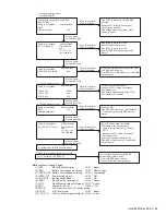
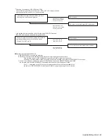
Over view:
When the Bluetooth function does not operate, use this flowchart to determine the problem.
I can not pair with the Bluetooth (BT) headset.
When an abnormal
condition is confirmed.
When an abnormal
condition is confirmed.
When an abnormal
condition is confirmed.
When an abnormal
condition is confirmed.
When an abnormal
condition is confirmed.
When an abnormal
condition is confirmed.
No
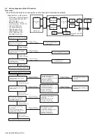
Major parts for a Bluetooth circuit
Bluetooth antenna (Pattern Antenna)
LC filter (L11)
Bluetooth/GPS (IC5)
Level conversion IC (IC6, IC7)
TCXO 19.2MHz (X1)
32.768kHz clock (X2)
33BT Regulator (IC3)
18BT Regulator (IC2)
MPU/DSP IC (IC706)
Replace any abnormal parts.
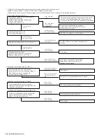
Verify the BT/GPS power supply.
(33BT) L4: 3.3V
Check the Module (BT/GPS) unit PCB side A.
Check the Module (BT/GPS) unit PCB side A.
Verify the ANT Matching Parts.
Visual check of L15, C68
(Whether not damaged)
[The BT/GPS power supply
line 33BT circuit is faulty]
L4, C15, C19, C20, C33
Replace any abnormal parts.
Check the Module (BT/GPS) unit
PCB side B (a).
Verify the BT/GPS power supply.
(18BT) L15: 1.8V
[The BT/GPS power supply
line 18BT circuit is faulty]
C18, C13, C31, L8, C39
Check the Module (BT/GPS) unit
PCB side B (b).
Verify the RTC for the BT/GPS.
X2 (3 pin): Square waveform,
32.768kHz,1.8Vp-p
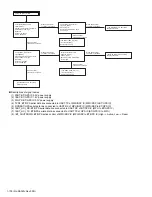
Make sure the BT headset have enough power?
Turn on your BT headset?
Put your BT headset into pairing mode?
Charge the BT headset. Turn on your BT headset and bring it
within one to two meters.
Try again pair with BT headset.
IC706
IC6
IC5
UART
UART
UART
L11
IC7
Pattern Antenna
PCM
PCM
PCM
MAIN UNIT
X1
X2
MODULE (BT/GPS)
UNIT
MPU/DSP
IC
BT/GPS
IC
TCXO
19.2MHz
32.768kHz
Clock
LC
Filt er
Bluet oot h
Ant enna
Level
conversion
IC
Level
conversion
IC
When a normal
condition is confirmed.
When a normal
condition is confirmed.
When a normal
condition is confirmed.
When a normal
condition is confirmed.
When a normal
condition is confirmed.
When a normal
condition is confirmed.
Replace any abnormal parts.
Verify the RTC Line circuit for
the BT/GPS.
Visual check of X2, L8, C39
(Whether not damaged)
Replace any abnormal parts.
Visual check of
the PCB side A parts.
Visual check of
the PCB side A parts.
(Whether not damaged)
(Whether not damaged)
Содержание NX-5700
Страница 106: ...MEMO ...
Страница 137: ...MEMO ...
Страница 138: ... No RA020 Rev 002 VSE Printed in Japan JVC KENWOOD Corporation Communications Systems Business Unit ...


