1-46 (No.RA020<Rev.002>)
4.8
Common Section
Item
Condition
Measurement
Adjustment
Specifications
/Remarks
Panel tuning
mode
PC test mode
Test-
equip-
ment
Unit
Ter-
minal
Unit
Parts
Method
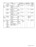
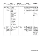
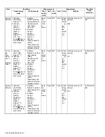
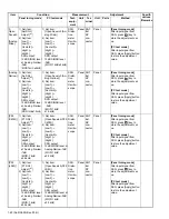
1.
Setting
1) DC voltage:13.6V
2) SSG standard modulation
[Wide] MOD:1kHz,DEV:3kHz
[Narrow] MOD:1kHz,DEV:1.5kHz
2.
Receive
Assist
1) Adj item:
[RAST]
Adjust:[****]
2) Adj item:
[Low1 RAST]
→
[Low2 RAST]
→
[Low3 RAST]
→
[Center1 RAST]
→
[Center2 RAST]
→
[Center3 RAST]
→
[High1 RAST]
→
[High2 RAST]
→
[High3 RAST]
Adjust:[****]
Press [ ] key
to store the ad-
justment val-
ue.
1) Adj item:
[Receive Assist]
2) Adj item:
[Low1]
→
[Low2]
→
[Low3]
→
[Center1]
→
[Center2]
→
[Center3]
→
[High1]
→
[High2]
→
[High3]
Press [Apply All] but-
ton to store the ad-
justment value.
Panel [Panel
tuning
mode]
[
],
[
]
[PC
test
mode]
[
←
],
[
→
]
[PC test mode]
[Automatic Adjust-
ment]
1) Press [Tune Assist
Voltage] button.
2) Press [Apply All] but-
ton to store the adjust-
ment value after the
automatic adjustment
has finished.
[Manual Adjustment]
[V] indicator on the PC
window shows VCO lock
voltage. Change the ad-
justment value to get
VCO lock voltage within
the limit of the specified
voltage.
Note:
Confirm the VCO lock
voltage approximately
3 seconds after the
adjustment value is
changed.
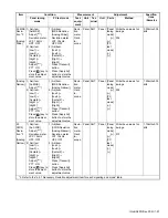
2.5V±0.1V
[Automatic Ad-
justment]
After the automatic
adjustment is per-
formed, verify that
the VCO lock volt-
age is within the
voltage range
which is specified
by the manual ad-
justment.
[Manual Adjust-
ment]
Press [Apply All]
button to store the
adjustment value
after all adjustment
point have been
adjusted.
Note:
The assist adjust-
ment value must
be between from
340 to 3550.
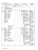
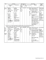
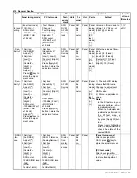
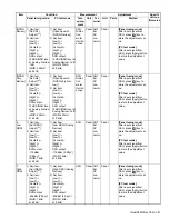
3.
Transmit
Assist
1) Adj item:
[TAST]
Adjust:[****]
2) Adj item:
[Low1 TAST]
→
[Low2 TAST]
→
[Low3 TAST]
→
[Center1 TAST]
→
[Center2 TAST]
→
[Center3 TAST]
→
[High1 TAST]
→
[High2 TAST]
→
[High3 TAST]
Adjust:[****]
PTT: ON
Press [ ] key
to store the ad-
justment val-
ue.
1) Adj item:
[Transmit Assist]
2) Adj item:
[Low1]
→
[Low2]
→
[Low3]
→
[Center1]
→
[Center2]
→
[Center3]
→
[High1]
→
[High2]
→
[High3]
PTT: Press
[Transmit] button.
Press [Apply All] but-
ton to store the ad-
justment value.
Panel [Panel
tuning
mode]
[
],
[
]
[PC
test
mode]
[
←
],
[
→
]
[PC test mode]
[Automatic Adjust-
ment]
1) Press [Tune Assist
Voltage] button.
2) Press [Apply All] but-
ton to store the adjust-
ment value after the
automatic adjustment
has finished.
[Manual Adjustment]
[V] indicator on the PC
window shows VCO lock
voltage. Change the ad-
justment value to get
VCO lock voltage within
the limit of the specified
voltage.
Note:
Confirm the VCO lock
voltage approximately
3 seconds after the
adjustment value is
changed.
2.5V±0.1V
[Automatic Ad-
justment]
After the automatic
adjustment is per-
formed, verify that
the VCO lock volt-
age is within the
voltage range
which is specified
by the manual ad-
justment.
[Manual Adjust-
ment]
Press [Apply All]
button to store the
adjustment value
after all adjustment
point have been
adjusted.
Note:
The assist adjust-
ment value must
be between from
340 to 3550.
Содержание NX-5700
Страница 106: ...MEMO ...
Страница 137: ...MEMO ...
Страница 138: ... No RA020 Rev 002 VSE Printed in Japan JVC KENWOOD Corporation Communications Systems Business Unit ...

