ZHEJIANG KAYO MOTOR CO., LTD.
www.kayomoto.com
- 53 -
1. AIR DISTRIBUTION MECHANISM
The timing driving sprocket on the crankshaft drives the timing driven sprocket on the camshaft
through the chain to rotate the camshaft. The cam drives the rocker arm with the rotation of the
camshaft, and the rocker arm overcomes the resistance of the valve spring to control the opening of
the valve.
2. COOLING SYSTEM
KT250 uses coolant to cool the engine. The coolant enters the engine from the water tank through the
water pipe, takes away the heat of the engine, flows back to the water tank, and then exchanges heat
with the air. After the coolant cools down, it enters the engine again to play a cooling role.
INSTALLING THE ENGINE
The installation steps are as follows:
1.
The engine is suspended on the frame (pay attention to protect the appearance of the engine).
2.
Install the carburetor on the intake elbow and fasten it with nuts and bolts.
3.
Install the throttle cable and air filter, the interface should be sealed, and the clutch control cable
should be installed.
4.
Install the transmission chain.
5.
Install the left rear cover or sprocket guard and fasten it with bolts. Pay attention to the outgoing
wire of the magneto.
6.
Install exhaust muffler. The M8 nut and the exhaust pipe sealing ring should be installed firmly
with a tightening torque of 10
~
15N•m, and the exhaust port should not leak air during
installation.
ENGINE MAINTENANCE AND ADJUSTMENT
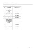
Inspection of installation bolts and nuts of cylinder head and cylinder block
The inspection is carried out at the first 1000km and every 5000km. When the engine is cold,
use a torque wrench to tighten the bolts and nuts to the specified torque.
TORQUE
M8
28
~
32N.m
M6
10
~
15N.m
CHECK THE VALVE CLEARANCE
The inspection is carried out at the first 1000km and every 5000km. Excessive valve clearance
will cause valve noise, and too small valve clearance will cause engine power drop and valve
damage. The valve clearance should be checked according to the above prescribed mileage, and
the valve clearance should be adjusted according to the following procedures:
Remove the valve cover.
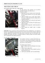
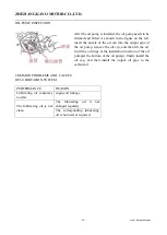
Unscrew the magneto plug and timing screw plug on the left front cover, and use a 14mm
socket wrench to turn the magneto rotor until the piston reaches the top dead center of the
compression stroke (turn the magneto rotor until the engraved line on the rotor matches the
left front cover Until the timing holes on the top are aligned).
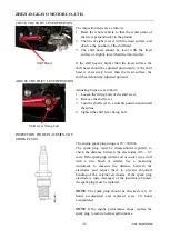
Insert a standard feeler gauge between the end of the valve rod and the adjusting screw on
the rocker arm. The clearance between the intake and exhaust valves is 0.03
~
0.05mm.
If the valve clearance is not within the above range, use a special tool to adjust it within the
specified range.

