


7 Maintenance
7.3.2
CEPH QC
NOTICE!
This program is available only for devices with cephalometric (CEPH) modality.
NOTICE!
The CEPH QC is an optional, yet recommendable, procedure and is mandatory to be
performed where local regulations require it.
1.
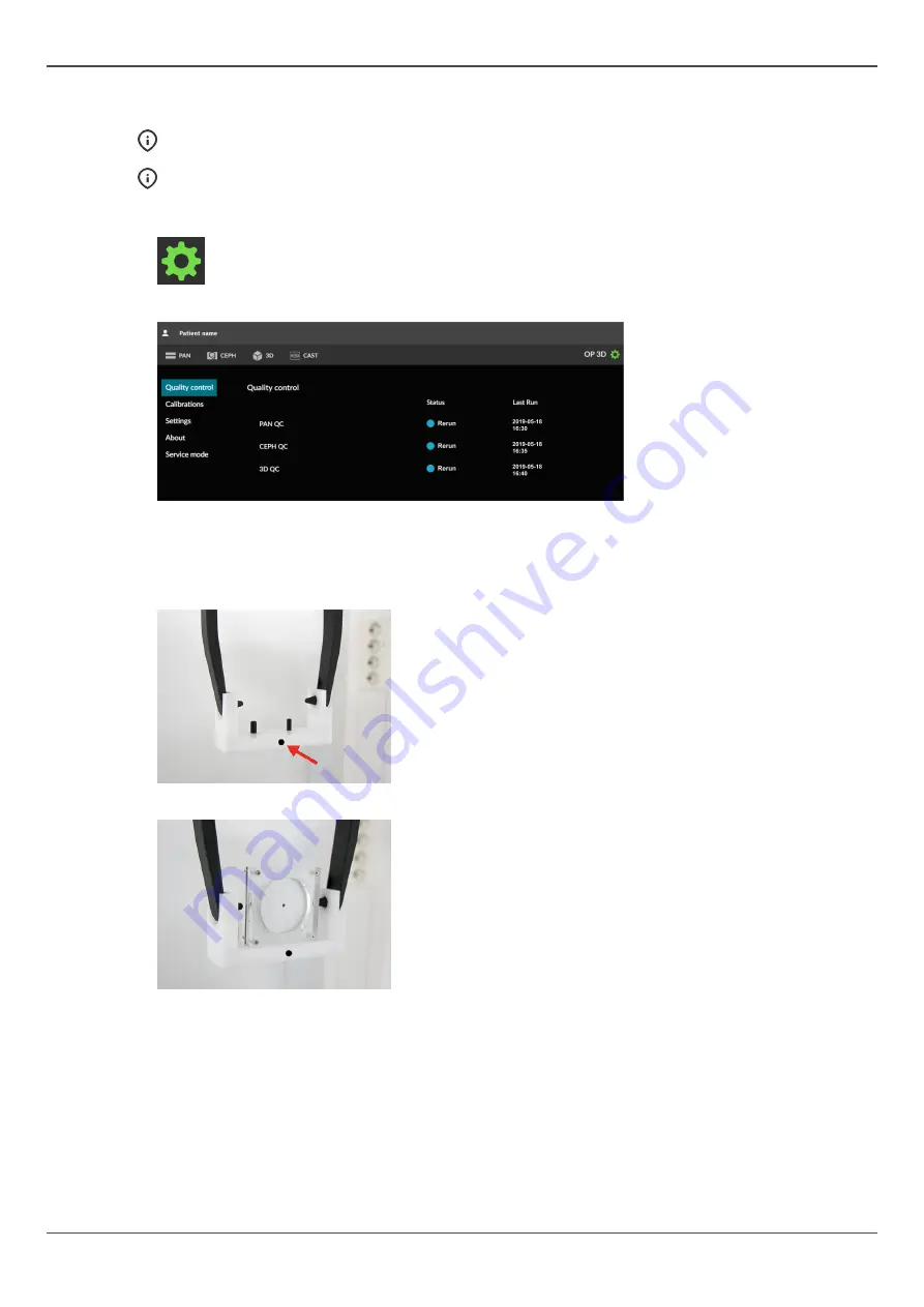
GUI:
Go to device settings.
2. GUI:
Select
CEPH QC
program from the
Quality control
menu.
3.
Turn the CEPH head support to
PA
position.
4.
Turn the nasion support aside.
5.
Attach the CEPH QC phantom holder to the ear rods so that the indicator on the holder faces the
CEPH tubehead.
6.
Attach the 2D QC test phantom to the CEPH QC phantom holder.
80
ORTHOPANTOMOGRAPH
™
OP 3D
Содержание ORTHOPANTOMOGRAPH OP 3D
Страница 1: ...Dental Excellence OP 3D ORTHOPANTOMOGRAPH OP 3D User Manual 212972 rev 30 0 805 4913 ENGLISH...
Страница 2: ......
Страница 49: ...6 Using the device 6 Using the device 6 1 General imaging workflow ORTHOPANTOMOGRAPH OP 3D 49...
Страница 106: ...9 Technical data 106 ORTHOPANTOMOGRAPH OP 3D...


