-16-
8.
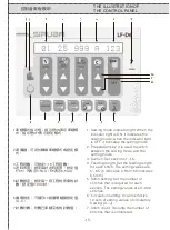
電源指示燈:顯示綠色指示燈表示可正常
車縫;顯示橘色燈表示有故障需排除;指
示燈
OF F
時,請確認電源開關是否開啟。
9.
取消鍵:可設定循環結束;可取消循環結
束;可載入原設定值。
1 0.
功能鍵:按此按鍵可進入系統參數設定
功能。
11 .
手動鍵:用手動方式觸動開關,以進入
下一段車縫工程。
12.
自動鍵:當車縫針數計數到達設定值
時,系統自動進入下一段車縫工程。
13 .
馬達轉動鍵:按此按鍵時馬達會轉動,
可用於送入或退出鬆緊帶。
P .S . :
參數
9
設定值為
0
:馬達轉動時,
可退出鬆緊帶。
參數
9
設定值為
1
:馬達轉動時,
可送入鬆緊帶。
1 4.
馬達停止鍵:按此按鍵系統會進入馬達
停止轉動模式。
P. S .:
在馬達停止轉動模式,按功能鍵
可進入測量縫紉機轉速功能。
1 5.
切刀鍵:按此鍵可在車縫段數間,執行
或取消切刀動作。
16.
增加鍵:增加設定數值。
17 .
減少鍵:減少設定數值。
1 8.
載入針數鍵:可在車縫設定模式,將計
數器所顯示的車縫針數,載入到該車縫
段的針數設定值,原有的針數設定值將
會被刪除。
8. Power light: When the light is green, it
indicates the normal sewing. When the
light is orange, it indicates that there is
a glitch which has to be eliminated.
When the light is OFF, check if the
switch is turned on.
9. Cancel key: It can end the circulation
setting; it can end the circulation
cancelling; it can load the original
setting value.
10. Function key: Press this key to enter
the parameter setting function.
11. Manual key: Turn on the switch
manually to enter the next section.
12. Automation key: When the number of
stitches is completed, the system
enters the next section automatically.
13. Motor operating key: Press this key to
start the motor, and the elastic tape
can be fed or withdrawn.
P.S.: parameter 9, setting value 0:
When the motor operates, the
elastic tape is withdrawn.
parameter 9, setting value 1:
When the motor operates, the
elastic tape is fed.
14. Motor stopping key: Press this key to
Stop the motor.
P.S.: When the motor stops operating,
press this key to enter the
function of measuring the
rotational speed of the sewing
machine.
15. Trimmer key: Press this key to execute
or cancel the thread cutting during the
sections.
16. Increase key: Increase the setting
value.
17. Decrease key: Decrease the setting
value.
18. Stitch loading key: In the sewing
setting mode, the number of stitches
shown on the counter can be loaded
to the stitch setting value of the
section, and the original stitch setting
Value is cancelled.
Содержание Siruba LF-D6
Страница 1: ...LF D6 使用說明書與零件圖 INSTRUCTION BOOK PARTS LIST ...
Страница 2: ......
Страница 12: ...組合圖 COMBINATION 控制組 1 Control Box 1 控制組 2 Control Box 2 控制組 3 Control Box 3 踏板開關 Pedal Switch 8 ...
Страница 14: ... 10 接管圖 WIRINGDIAGRAM ...
Страница 33: ... 29 ...
Страница 34: ... 30 ...
Страница 35: ... 31 ...
Страница 36: ... 32 ...
Страница 37: ... 33 ...
Страница 38: ... 34 ...
Страница 39: ... 35 桌板圖 TABLE CUT OUT OF 747S T5 ...
Страница 40: ......
Страница 41: ......


