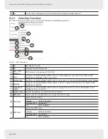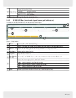
90 of 122
Operating the Reader Using the ReaderStart Software
14.6
GPIO Functions
Readers with GPIO functionality
1)
offer the possibility to set up small controls which trigger the reader, for instance by
means of a light barrier, or which trigger an action at the outputs of the reader by reading specific tags. Such an action
can switch an output to control the flow of goods.
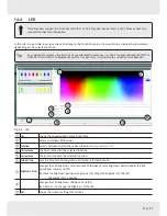
The GPIO tab allows the reader to interact with its environment. The GPIO function tab allows the user to manually read
or switch inputs and outputs of the respective application. For more complex procedures, it is possible to create action
lists which execute a sequence of commands on the reader. This list can then be linked to various inputs.
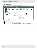
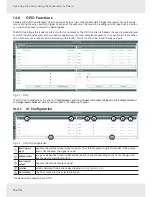
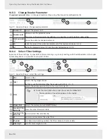
Fig. 51: GPIO
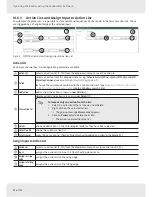
The GPIO tab is divided into 3 sections,
IO Configuration
, consisting of
Input
and
Output
,
Test Input
and
Test Output
,
Action List
and
Assign Input to Action List
which are described in the following chapters.
14.6.1
IO Configuration
2
8
1
3
4
5
6
7
9
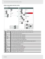
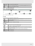
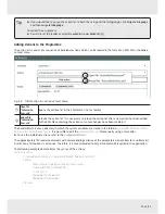
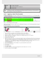
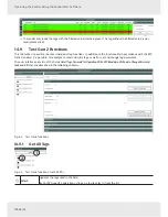
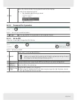
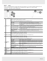
Fig. 52: GPIO: IO Configuration
Invert logical
input
negates the electrical input signal and uses this state for processing in the reader; if the param-
eter is not checked, the signal is used
ཱ
Debounce time
assigns a debounce time in milliseconds to each channel depending on the sensor being used
(mechanical or electrical switch)
ི
Invert logical
output
negates the electrical output signal
ཱི
Function
selects between the functions described in
Selecting Functions, p. 88
ུ
First antenna
the first antenna for the selected function
1)
All Generation 3 readers have GPIO.
Содержание ARU 3 Series
Страница 121: ...121 of 122...

