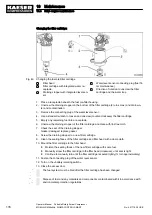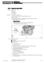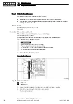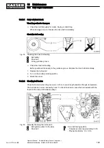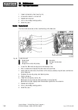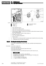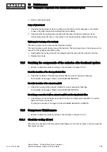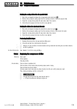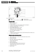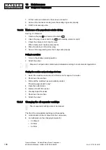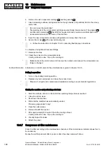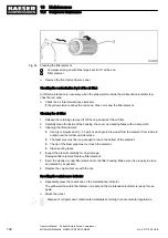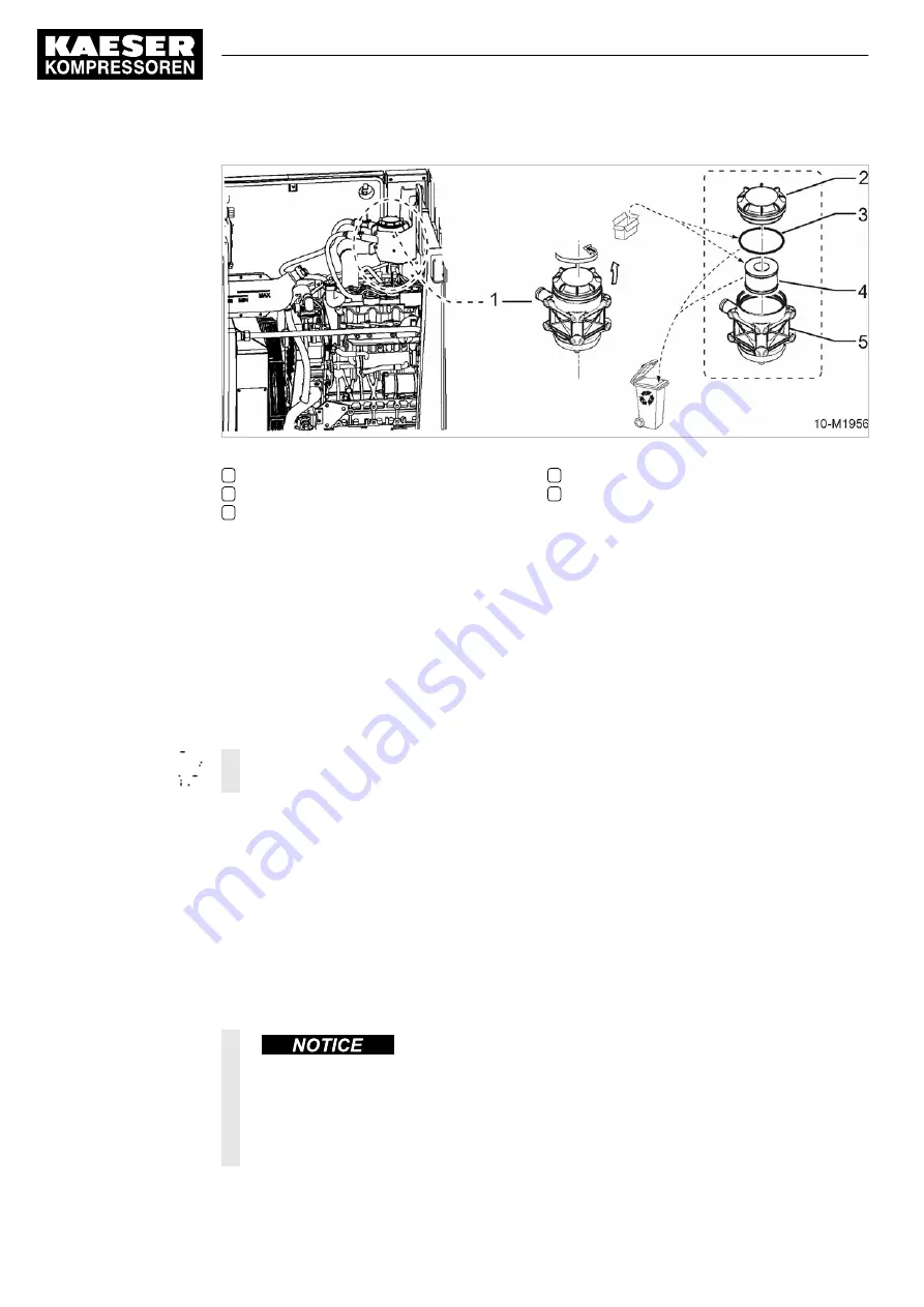
Fig. 57 Change the oil separator element
1
Oil separator
2
Cover
3
Sealing ring
4
Oil separator element
5
Enclosure
1. Remove the left-rear panel.
2. Unscrew the cover and place aside.
3. Remove the oil separator element and the sealing ring.
4. Clean the contact surfaces of enclosure and cover with a lint-free cloth and remove any adher‐
ing oil and grease residue.
5. Insert a new oil separator element and new sealing ring.
6. Manually screw the cover on.
7. Turn on the «battery isolating switch».
8. Attach the panel.
Dispose of the old oil separator element, sealing ring and contaminated resources according
to applicable environment protection regulations.
10.4.11 Checking the fastening of the fuel tank
The machine is equipped with a fuel tank or tanks. These are fastened with lashing strips and
ratchets.
Precondition The machine is switched off.
The machine is standing level.
The machine is fully vented, the pressure gauge reads 0 psig.
The machine has cooled down.
All compressed air consumers are disconnected and the air outlet valves are open.
The lashing strip of the fuel tank is overly tightened.
The plastic tank can be damaged by excessive tightening of the lashing strips.
The fuel tank may burst and spill.
➤ Do not over-tighten the lashing strips.
➤ Slightly hand-tighten the lashing strips.
10 Maintenance
10.4 Drive engine maintenance
130
Operator Manual Portable Rotary Screw Compressor
MOBILAIR M58utility SIGMA CONTROL SMART
No.: 901779 08 USE

