background image


61 


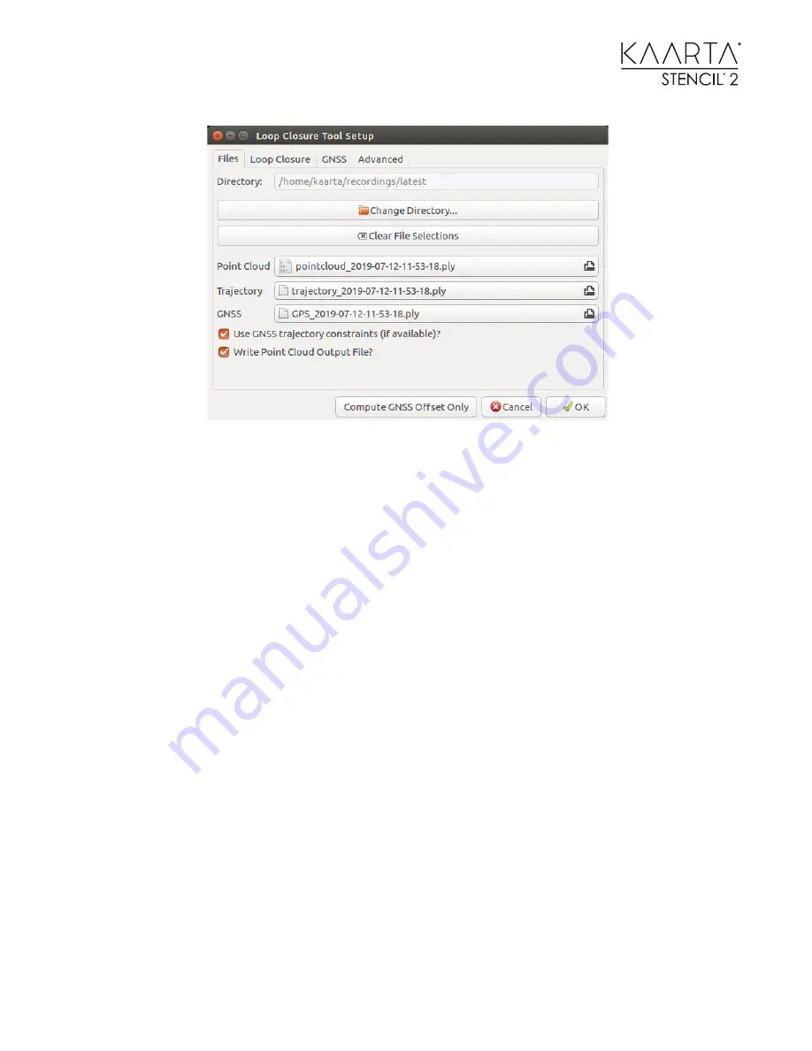
The files are auto-populated from the latest scan folder. In this example, there was no GPS file, so 
it is left blank. If you click on the Change Directory button, you can select a different sub-folder to 
use, if it is not from the latest scan. It should auto-populate the files from that sub-folder. If you 
want to choose another point cloud, trajectory or GPS file from that sub-folder, you can use the 
file browser button next to the file names. 

The checkbox for Write Point Cloud Output File? allows you to run the Loop Closure Tool to find 
the best correlation results by comparing the Stencil and GNSS trajectories without having to wait 
for the point cloud file to be written. Once you have the parameter set you want, you can run the 
tool one more time to write out the point cloud. This can speed up the process in determining the 
specific parameters that work best for your dataset. 

If you do not want to use the GPS data in the loop closure process, you can uncheck the Use GNSS 
trajectory constraints (if available)? checkbox 

The second tab lists options and parameters related to overlapping trajectories. If you are only 
interested in global alignment of the data using GNSS data, you can deselect the “Enabled?” 
checkbox and move to the third tab. 

Содержание STENCIL 2

Страница 1: ...WWW KAARTA COM USER GUIDE ...

Страница 2: ...information and updates www kaarta com O V E R V I E W Kaarta Stencil 2 is a low cost customizable mobile mapping platform for rapid mobile scanning a computer small enough to fit in your hand but powerful enough to process and view any of the data it captures C A R E Like any precision instrument take precautions to ensure a long useful life of the device Treat it with care Avoid rough handling d...

Страница 3: ...ld better point clouds and trajectories Easier localization Localization map is displayed prior to moving for quicker identification of initial pose Improved data post processing CCC Builder Alpha Release New Tool to perform CloudCompare operations without using CPU resources for visualization LAS file generator Export a binary LAS file from a Stencil point cloud LAS file merging Easier merging of...

Страница 4: ...or reporting output stats from Loop Closure Tool more data in the scan_info files and logging of Processor data during scanning replay to help debug customer issues Adaptive Data Replay Improved interface Ability to start single step pause at and stop replay from parameters Standalone tool sets Mapping Localization and with without camera modes within the dialog box Kaarta Cloud integration Upload...

Страница 5: ...ndicator 12 Power Operating Mode Buttons 13 Using Stencil 2 Out of the Box 14 Before You Begin Mapping 14 Start Mapping 14 Stop Mapping 14 Scan Folder Contents 15 Chapter 2 18 Stencil 2 Operations 18 It s a Computer 18 Using the iPad 18 Desktop Icons 20 Tool Icons 22 Mapping with the Feature Tracker 24 Feature Tracker Best Practice 25 Recording Color Images while mapping 26 Using the Mode Switch I...

Страница 6: ...ng point clouds from other programs 50 Chapter 4 52 GNSS Operations 52 Integrating GNSS with Stencil 52 GPS Setup 52 GNSS Monitor Status 53 Syncing Stencil Clock to GNSS time 53 Finding the USB port on Stencil 2 if not known 53 Recording GNSS Raw Data to use for PPK Processing 54 Processing PPK Data 54 Using the loop closure tool overview 55 Key Poses and Geo locating point clouds 56 Loop closure ...

Страница 7: ... 79 General 79 Handheld scanning Indoors 80 Handheld scanning Outdoors 80 Vehicle Mounted Scanning 81 Aerial Scanning 82 Request for additional Scanning Tips 82 Problems Issues 83 ply file error or non generation 83 Sun glare 83 Double registration 84 Small rooms narrow hallways 85 Reflections 86 Darker Brighter Environments 86 Using CloudCompare 87 Visualization basics 87 Colorize Point Cloud by ...

Страница 8: ...ameters to set 122 Appendix IV 124 Working with ROS 124 Mode switching commands 124 Start Stop mapping using ROS commands 124 Creating a reference map for localization 124 Remote commands not supported 125 Coordinate transforms for localization 125 Important localization topics 126 Reporting global position during localization 126 Localizing based on current GNSS location 126 Sensor Calibration 12...

Страница 9: ...ng Computer to Stencil 2 ROS Master 139 Echoing the Localization topic 139 Showing map camera and pose information using RVIZ 140 Synchronize Stencil 2 To Computer Time 140 SSH to Stencil 2 141 Mapping and Localization Confidence 141 Appendix VII 142 Troubleshooting 142 Appendix VIII 143 Previous Software Release Notes 143 ...

Страница 10: ...ounting Plate 4 Feature Tracker 5 Velodyne Lidar Sensor including documentation on the Kaarta USB drive 6 Velodyne Interface Box AC Supply and country adapters not shown 7 Battery Pack 23 000 mAH US shipments only 8 Battery Pack Charging Accessories Use this charger only for battery charging 9 Feature Tracker Cable Installed 10 Velodyne Inline Connector Installed 11 USB Status Indicator 12 Kaarta ...

Страница 11: ...Power Input 3 Power Input Operating Switch left button 4 HDMI Port miniDisplayPort 5 Velodyne Connector Port 6 Ethernet Port RJ 45 7 Velodyne Switch right button 8 Two USB3 Ports back 9 Thunderbolt Port HDMI miniHDMI 10 Two Air Vents 11 MicroSD card slot No MicroSD card slot on S N s 100 12 Two USB3 Ports front 13 Feature Tracker 14 Velodyne Lidar Sensor ...

Страница 12: ...Localization in progress and GNSS data is saving It is best to wait about 5 seconds after blinking starts before moving Note When using GNSS teal denotes a fix quality 1 or more during mapping or localization If the fix quality is 0 the light is Green and no points are saved in the GPS ply The indicator may change between teal and green throughout the data collection Yellow Blinking Down sampling ...

Страница 13: ...y booted up After power to Stencil 2 is on and Lidar is on for at least 60 seconds press the left button once to Start Mapping Localization Press again to Stop when mapping localization is complete Wait for the yellow USB indicator to stop blinking and turn blue You can repeat mapping localizing in this fashion Once you have finished and the USB indicator is blue you can press the left button twic...

Страница 14: ...g needs your attention Turn on Stencil 2 and the Lidar You ll know they are on if the LED status ring around each push button and the USB indicator is blue Note Ensure that both Stencil 2 and the Lidar are both powered on for at least 60 seconds before you begin mapping S T A R T M A P P I N G To begin mapping press the Stencil 2 power button once Wait until the USB indicator turns green and begin...

Страница 15: ...ts and information related to the GNSS data available during the scan scan_info_xxx yaml Yaml file containing information during scanning playback used by the Loop Closure Tool and during Localization Using GNSS Tool pointcloud_xxx_ds ply Downsized binary point cloud file created during mapping localization as specified in the parameter file configuration_xxx yaml Stencil 2 configuration parameter...

Страница 16: ...tencil 2 supports exFAT drives for transferring files larger than 4 3GB Using USB3 drives reduces the time for data transfers Be sure to copy data off of Stencil periodically to ensure disk space for future scans T Y P I C A L S C A N _ I N F O T X T F I L E W I T H G N S S D A T A ...

Страница 17: ...shading so the point cloud is easier to view In CloudCompare save the point cloud files in other formats such as las This is helpful for some workflows using CAD software See the section on Command Line Tools for converting to las without using CloudCompare Out of box mapping is the most basic way to create a 3D scan Next we will explore the powerful features and functions of Stencil 2 ...

Страница 18: ...n the monitor cable to prevent damaging the Stencil 2 connector for Stencil S N s 150 U S I N G T H E I P A D When processing data in the office Stencil 2 conveniently works with a computer monitor keyboard and mouse But this set up is not practical for in field use so Stencil 2 comes with an iPad for changing operating modes and starting stopping scans The iPad bundled with Stencil 2 is pre paire...

Страница 19: ... options window Choose between touchscreen interface or mouse interface Touchscreen moves the cursor to follow your finger on the screen Mouse lets you move the cursor on the screen by how you move your hand on the screen even though the two are not in the same place When using mouse mode move the cursor to the desired option and then select to select the option ...

Страница 20: ...he modes as well as providing a user interface to the many Stencil 2 features S T A R T S T O P The Start Stop icon is a large play icon that starts and stops mapping localization according the mode set and visually changes depending on whether you started mapping localization or stopped mapping localization ...

Страница 21: ...e Playback Raw Data and Record Images Icons The Record Images icon appears grey with a red dot center when saving data images are disabled The icon turns green with red dot center when saving data images are enabled The raw data images are only saved while running one of the six operational mapping localization modes ...

Страница 22: ... Plot Plot showing the mapping confidence value and threshold and a plot showing the localization confidence Localize using GNSS Allows the user to localize using the current GNSS value if a geo registered map was loaded Record KeyPose Allows the user to record specific waypoints in Stencil trajectory coordinates and GNSS coordinates if available Choose Map for Localization Selects a map to use as...

Страница 23: ...r s Guide older training slides for Stencil 2 which may be helpful the chrony conf file for synchronizing to a computer a radian circle mounting dimensions in a pdf file Stencil 2 spec sheets and the as shipped user and playback default files if you need to restore these sections to the as shipped configuration recordings This is the main folder that contains mapping localization replay post proce...

Страница 24: ...see the difference W H E N T O U S E F E A T U R E T R A C K E R Use Feature Tracker if you are mapping environments with minimal structures such as large open areas or if you are mapping structures that require significant tilting to capture such as high rises or complicated structures Below are two examples where having Feature Tracker turned on produces the best mapping results Following the co...

Страница 25: ...or best performance of the feature tracking capability Try not to occlude the camera image with the operator The Feature Tracker should not be used in situations with varying lighting conditions and especially in low light situations The Feature Tracker should never be pointed towards the sun When using the Feature Tracker take care to avoid situations where dynamic objects such as people or vehic...

Страница 26: ...y are Image saving rate Image horizontal resolution not used in with_camera modes Image vertical resolution not used in with_camera modes The Record Images will create a sub folder with the time stamped images and also create an avi movie file in the scan folder U S I N G T H E M O D E S W I T C H I C O N S There are six Mode Switch icons located on the upper the left side of the screen These chan...

Страница 27: ...s in the environment or when tilting the scanner for vertical buildings towers or aerial payloads Stencil 2 ships with the ability to create detailed maps and provides 6 DoF real time odometry x y z roll pitch and yaw at 200 Hz with less than 15 msec latency To create 3D maps most users do not need to know the details about odometry and localization Stencil 2 orients itself with respect to a prior...

Страница 28: ...Camera Mapping with the Feature Tracker based on a prior map Localizes when there are sparser features in the environment or when tilting the scanner or for aerial payloads Localization from Last Mapping based on a prior map from ending position Start localizing where it previously stopped when the first map ended Localization with Camera from Last Mapping with the Feature Tracker based on a prior...

Страница 29: ... it When you use the Window Manager to switch to one view it will enlarge whatever is in the larger view to fill the window and hide the smaller view The Stop Button is the same as pressing the Stencil Stop button The Disk Space Status Bar shows the current amount of memory that is used teal and free The View Zoom Settings gear will bring up the following menu of options Window Manager Stop Button...

Страница 30: ...ll show an isometric view where you can rotate along any axis The magnifying glass switches between various zoom levels so you can zoom in or see the full extent of the point cloud or something in between These view settings make using the iPad a little easier when monitoring the scanning operation ...

Страница 31: ...31 Here are a couple of the variations described ...

Страница 32: ... New folders at the top level are only created when conducting a new scan when replaying a raw data bag file or when converting old Stencil files to the new Stencil 2 format The top level scan folder names can be changed to make it easier to recognize and organize scanning files An example of the top level directory is shown here The following picture shows the typical files generated when mapping...

Страница 33: ...33 Summary scan information can be found in the scan_info txt file as shown below Note that the lines indicating GPS Stats only appear in the file if GNSS data was available while mapping or localizing ...

Страница 34: ...allows the user to increase overall map accuracy by minimizing drift in the baseline map This approach eliminates the registration step required when merging maps This feature extends the environments that can be successfully mapped As an example you could build a ground based map and use that as the reference map for filling in more details or trying to map higher structures with less 3D features...

Страница 35: ...txt file by editing the Last_pose txt file with the desired starting location saving it and selecting it when using the Choose Last Pose Icon The first two lines are comment lines and not necessary for the file xyz are in meters Yaw pitch and roll are in radians Normally you can set pitch and roll to zero In addition to the map created during mapping and localization there is an associated traject...

Страница 36: ...cause Stencil to stop registering against the data collected so far and start a new map segment This can always be adjusted in the replay parameters as needed to produce better results Usually best to leave the threshold at 0 for live scanning This mapping confidence parameter stored in the trajectory ply file is also used in the Loop Closure Tool to control how data is added registered to the map...

Страница 37: ...37 See flow chart below for additional insight on mapping and localizing with Stencil 2 ...

Страница 38: ...g paths in the trajectory even if you do not start and stop at the same location but even more so if you do Overlapping trajectories are not necessary if GNSS data has been recorded by Stencil for this scan This tool is described in detail in the GNSS Operations portion of this Users Guide S H A R P E N I N G T O O L The Sharpening Tool compresses flat surfaces This reduces the repeatability blur ...

Страница 39: ...nt cloud you will have to manually select it in the next window Level Pointcloud Automatically levels of the point cloud Don t check this box if the file has already been leveled and you are running this tool multiple times on the slices to vary the cleaning parameters Save Leveled Cloud Saves the full size point cloud for other uses It avoids re running this step if using this tool multiple times...

Страница 40: ... meters to eliminate the floor from cleaning and final image generation These pairs can overlap For example specify 0 2 1 5 and 0 2 2 0 Generate as many slices as you want but there must always be an even number of elements pairs in ascending order If there are an odd number of pairs or descending order one of the following error screens will come up Gridstep m Subsamples to use in the sections by...

Страница 41: ...us to look for neighboring points Clean Min K the minimum number of neighbors in radius to keep the point Image file type Specifies the 2D rendering file type Known supported types are pgm png tiff jpg and bmp other types may also be supported The floor planner generates a leveled point cloud the leveled sections and two image files as specified by the user for each slice One image file is in blac...

Страница 42: ...This would typically be run if Stencil shutdown unexpectedly due to a power failure rosrun clay_launch generate_scan_info_txt sh filename of scan_info yam output filename Fix ply vertex count This utility is used to repair ply files that have incorrect vertex numbers This would typically be run if Stencil shutdown unexpectedly due to a power failure rosrun kaarta_io fix_ply_vertex_count filename o...

Страница 43: ... you do not select a file that may be selected in one of the other three checked box names To do a quick check just use the trajectories the first time through and if you like the result don t select trajectories the second time through but select the point clouds and gps files For each ply file _offset will added at the end of each name No existing files are modified Also a scan_info_offset yaml ...

Страница 44: ... times rosrun stencil_scripts update_2018_2019 sh A dialog box will appear with options for selecting the source directory for the older files If the boxes do not auto populate you can manually select the files you want The point cloud file will be converted to binary The point cloud trajectory and GPS file headers will be used to generate the scan_info yaml file The trajectory GPS Last pose and b...

Страница 45: ...st processing tools Modify timestamp of every point in a ply file This utility provides an easy way to change the time offsets in any of the Kaarta ply files rosrun kaarta_io modify_ply_time filename input filename output time offset Down sampling large point clouds by time This utility will down sample a point cloud by time to the number of points in the rosparam set command rosparam set velodyne...

Страница 46: ...rper point clouds The results from live scan and Adaptive Data Replay include x y z data with time and intensity This command line tool generates normals planarity curvature confidence and four filtering scalars KF_1 KF_2 and KF_3 which get used in the point cloud filtering command line tools below You can load these into CloudCompare and vary them individually to see how they affect the overall s...

Страница 47: ...ance m Varying the Sharpening Search Distance impacts the time needed for processing 0 2 is good for outdoor scans 0 1 for indoor Color by Intensity When selected the pointcloud ply file will contain greyscale RGB values by enhancing the color dynamics of the intensity scalar field using the RGB IHS method Level When selected this software will search for the floor plane and level the point cloud ...

Страница 48: ...ich can be embedded in script files will get a value of a key in the yaml files This is useful for reading the global offsets in the yaml file rosrun kaarta_io getScanInfoValue key scan_info yaml filename or to get the value during scan operation live or playback rosrun kaarta_io getScanInfoValue key 0 Set the value of a key in a scan_info yaml file or during a scan This script which can be embedd...

Страница 49: ...thout bringing up the visual elements of CloudCompare This greatly increases the size of point clouds you can work with A simple example is shown here A point cloud was selected using the Browse button Subsampling SS was selected in the Available Commands window The Add button was used to move it to the configured Commands window Clicking on the SS in the Configured Commands window brings up the S...

Страница 50: ...he same header format as Stencil 2 as shown below The vertex number should equal the number of points in the point cloud If you do not have intensity or time data just set the values to 0 0 or exclude the field in the header and the data in the ply file Only the XYZ points are necessary to create a map for localization ply format ascii 1 0 element vertex 30000000 property float x property float y ...

Страница 51: ...ecord the 4 X 4 translation matrix to be used to reset the location of the new point cloud collected during localization to the original coordinate system Do this by applying the inverse of the 4 X 4 matrix in CloudCompare to the original or the map created by localization This option is a check box in the Edit Apply transformation input box Using Circle_Centered obj to determine origin of other p...

Страница 52: ...obal drift error correction If the antenna is small enough it can be mounted to the top of Stencil 2 using double sided tape etc If it is larger you may need to build a suitable frame for mounting the larger antenna such as shown Kaarta provides a GNSS solution using the Emlid Reach units fully integrated with Stencil 2 and available for purchase Contact info kaarta com for a quote if desired Kaar...

Страница 53: ...O W N If the GNSS device is not on the default ttyACM0 port you may be able to access it on dev ttyACM1 dev ttyUSB0 or dev ttyUSB1 using the cat dev ttyXXXX as shown above where XXX is the port number Once you have determined the correct port number you can select the GNSS Monitor Icon and enter it in the dialogue box Note Some GNSS units only work over RS232 which may not register immediately on ...

Страница 54: ...grating Stencil with the Trimble BX 992 GNSS System P R O C E S S I N G P P K D A T A In the US using the CORS data Example Using Trimble BX 992 Stencil needs to be connected to the internet to connect to the CORS database Using the BINEX file produced as described in the previous section open a terminal window and run the following command in the scan folder rosrun receive_gps binex2GPS sh BINEX ...

Страница 55: ...h The Loop Closure Tool tries to match the starting and ending scans to each other if you have indicated the same starting and ending location and includes the orientation as well if you were facing the same direction at the start and end The amount of error corrected when a match is found is back propagated linearly across the trajectory path Drift corrections can be done even if you did not star...

Страница 56: ...s to align the trajectory with the GNSS coordinates while still maintaining accurate scan matching between frames This process changes the point cloud as necessary to match the global coordinates thus removing drift throughout the dataset If you have survey GNSS data such as Ground Control Points GCP but no trajectory or time estimates you can still geo locate your point cloud using CloudCompare e...

Страница 57: ... 761880 279 389000 Load the text file into CloudCompare as a point cloud Once you have identified the physical features in the point cloud that correspond with the GCPs in the text file use CloudCompare to align them as described here 1 Select both point clouds in the left menu box then use the Align point pairs picking tool under the Registration submenu to associate the GCP with the correspondin...

Страница 58: ...n see the effect of scaling on the error terms and choose to add scaling to the geo location process As a rule do not scale as it distorts the finished cloud to match the points more closely 4 You can also set what rotation or translation is allowed when you align the clouds When you are finished be sure to save the geo registered cloud in your desired format ...

Страница 59: ...nts but is less useful in fixing significant drift or twists in the trajectory due to bad visual odometry estimates due to occlusions or large moving objects in the field of view These are best fixed in the replaying of raw data by adjusting the parameters as well as confidence thresholds and the visual odometry rejection parameters to generate better results The replay of raw data also allows bet...

Страница 60: ...e easier to edit for the final go round A lot of GNSS data is collected at 5 or 10 Hz but you really only need data from 5 10 meters apart to accurately align the Stencil trajectory to GPS L O O P C L O S U R E T O O L S E T T I N G S The Loop Closure Dialog box is divided into four tabbed sections In addition to the OK button to start the loop closure process and the Cancel button to terminate th...

Страница 61: ...ure Tool to find the best correlation results by comparing the Stencil and GNSS trajectories without having to wait for the point cloud file to be written Once you have the parameter set you want you can run the tool one more time to write out the point cloud This can speed up the process in determining the specific parameters that work best for your dataset If you do not want to use the GPS data ...

Страница 62: ... the Match Distance where the start and stop location is not the same is to measure the distance between the same object in the point cloud seen at different time By looking at your point cloud by time you can see the same object as two colors separated by some distance You should set the Match Distance to be 50 larger than the largest Match Distance you can see in this manner Four meters is a goo...

Страница 63: ...k like of poses per stack 20 This is the number of 5 Hz scans to stack together before matching back to the registered map being built 20 scans represent about 4 seconds while 5 scans represent about 1 second The default 20 can be used for slower scanning speeds such as walking Change it to 5 for driving applications The Min will only be used if you are filtering data using the Pose Stack Confiden...

Страница 64: ... the Loop Closure Tool runs and you do not see any differences it may be that the patches are too sparse as in some hallways or underground scans you can reduce this number to try aligning sparser patches End at start point Check this box if you ended your scan near the same spot as the start of the run Setting this to true if it is true means you can keep your gap distances smaller in the Match D...

Страница 65: ...g factor Since GNSS elevation data is less accurate than the horizontal data it is common to use different weighting factors for each Minimum Point Spacing 5 0 m This value sets the point spacing between GNSS points to select for use in loop closure Setting this number too small tends to significantly increase processing time and adds choppiness blurring to the scan matches GNSS systems produce mo...

Страница 66: ...ment Method which is more suitable for slower speeds and for data collected while walking or in cases where you come back to the beginning of the scan It is less suitable for longer linear type scans The Displacement Method tracks the current location from the origin of the scan and calculates the best match between the Stencil 2 and the GNSS trajectories The third additional method is the Speed M...

Страница 67: ...prove your results Edit the GNSS data directly to eliminate bad points You can do this with a text editor or in CloudCompare After running the loop closure tool once there is a file of the GNSS data used for Loop Closure It might be easier to edit this loop_closed GPS file than the full file You do not have to have lots of GNSS points to accurately reduce eliminate global drift errors Filter the G...

Страница 68: ...SS points selected for loop closure last_pose_loop_closed txt updated last pose file after loop closure pointcloud_ timestamp _loop_closed ply modified point cloud after loop closure pointcloud_ timestamp _loop_closed_stats ply Statistics generated by the loop closure process to indicate how well the loop closure process worked trajectory_ timestamp _loop_closed ply modified Stencil trajectory tak...

Страница 69: ...sure The picture at the top is the GNSS data showing dropouts over the course of the data collection The picture at the bottom is the trajectory data from Stencil 2 The starting and ending locations were the same As you can see there were some issues with Stencil 2 trajectory as the trajectory end points do not match ...

Страница 70: ...L O S U R E T O O L E F F E C T The next two images show the effect of the loop closure tool The first image is an intersection that the vehicle passed through three times before correction Note that one of the times the vehicle passed through this intersection it was not correctly registered ...

Страница 71: ...age shows the same intersection after loop closure was applied Note that all three passes through the intersection are correctly registered This last image is the point cloud file overlaid on the a map from maps google ...

Страница 72: ...as recorded while mapping with a reflector on top of Stencil 2 To use GNSS data logged separately or non GNSS data the data will need to be formatted to fit the Stencil gps_202X xxx ply format The GPS_x GPS_y and GPS_z values are from the GNSS unit at the times shown The key here is to determine the time offsets between the Stencil 2 values and the GNSS values to create this gps_202X XX ply file T...

Страница 73: ...86 100 991 2 1 2018 10 41 07 AM 103 4999 971 6925 898 100 987 2 1 2018 10 41 08 AM 104 4999 964 6925 904 100 977 2 1 2018 10 41 09 AM 233 5083 435 7013 203 101 179 2 1 2018 10 43 20 AM 234 5082 761 7013 233 101 126 2 1 2018 10 43 21 AM 235 5081 990 7013 079 101 140 2 1 2018 10 43 22 AM The information here is in the format of index X Y Z date and time This data would need to be converted to the gp...

Страница 74: ...ame point during scanning and the trajectory shows a gap between the start and end you will need to fix this in loop closure By colorizing the point cloud by time or scalar index you can look at the overlapping paths and verify that all 3D structure is registered correctly to each other for each time at that point If you do not see any double registrations and there is no gap between the starting ...

Страница 75: ...ring heights closely spaced you may need to reduce the Vertical Region to 1 or 1 5 so you do not end up matching different floors to one another If all issues were not fixed try running again with different parameters You can either run it again on the original point cloud and trajectory or on the previously loop closed results Left Point cloud before loop closure Right After loop closure was run ...

Страница 76: ...r to the right of the file name Select a localization mode can be with camera or without Start localization at origin of the prior map Alternately if starting where Stencil 2 was stopped in the last mapping localization run choose from last You should also select the last pose for the map Change blindRadius to a value that represents the vehicle radius to exclude the vehicle points from the map If...

Страница 77: ...based map by hand holding Stencil 2 or mounting it to a ground vehicle and moving around the structure Verify the map has no drift Run Loop Closure if needed Use Choose Map for Localization Choose a localization mode with Camera is REQUIRED for aerial applications Start mapping at origin or the end of the ground based map depending on the localization mode selected by mounting Stencil 2 to a Drone...

Страница 78: ...78 Note If the environment has little 3D structure set useMatching to false important during aerial localization not necessary for ground based mapping ...

Страница 79: ...mitting to a longer scan Shorter paths that cross are better than a longer single path If you can scan a place that you will return to sooner it will decrease overall map drift For example in the diagram below it is better to start at 1 rather than 2 If you must start at 2 move to 1 and back to 2 before proceeding to capture more of the scene Use the IPad with Stencil 2 for real time feedback on t...

Страница 80: ...nts to show up on the monitor or status light to be blinking green then rotate Stencil 2 slowly while rolling and pitching slightly before moving around to build a denser base map to start from When transitioning between larger rooms or turning corners move a little slower to build up the new area before proceeding Make turns with the LIDAR level to the floor Don t turn and tilt at the same time D...

Страница 81: ...l drift you will get Do not occlude the front or back of the sensor Adjust the blindRadius to eliminate any portion of the support structure or vehicle from the scan Use the ignorePolygon parameters in Stencil Settings to remove any portion of the image that is not moving In this image a polygon has been defined in red The top left corner of the image is 0 0 The bottom right corner is 320 320 This...

Страница 82: ...dar data from being added to the map A E R I A L S C A N N I N G The feature tracker must be used for aerial scanning Mount Stencil at angles up to 75 degrees Don t fly too high 60 meters Focus on Mission Planning Fly only over 3D structure Flat fields will cause the algorithms to fail Fly smoothly and limit rotations to 30 deg sec Smooth takeoffs and landings Record raw data This will allow repla...

Страница 83: ...nd of a data collection it may be recovered by using the tools described in the Post processing Command Line Tools section of this manual S U N G L A R E On sunny days the sensor can generate additional points that look like a spray in the registered point cloud The only way to fix these is to remove them manually from the data set using the scissor or segmentation tools ...

Страница 84: ...ck of 3D structure in the scene Excessive dynamic motions To address issue 1 Stencil 2 comes with a loop closure tool The images below show the same data set before left and after right Issue 2 is corrected by cutting the point cloud at the twist and remerging the two clouds correctly This is described in the Cleaning and Merging Ply Files section later Issue 3 is resolved by finding more suitable...

Страница 85: ...s high level of accuracy but every modeling system has limitations Be sure to read the Typical Parameters to Set section for maximizing the chance for success in small areas In particular mobile mapping systems have difficulty handling extruded environments Smaller rooms tunnels sewers and narrow hallways are constrained in two axes but are unconstrained along the third axis see diagram below This...

Страница 86: ... R O N M E N T S If you need to do Mapping Localization with Camera in darker or very bright environments you can open close the F Stop on the feature tracker to let in more light or limit the amount of light through the lens Normally it is set to F 4 Stencil 2 uses an auto exposure algorithm to maximize the dynamic range but in environments outside the normal limits of darkness brightness you can...

Страница 87: ... if necessary through the snap interface V I S U A L I Z A T I O N B A S I C S You may have to modify the instructions in this manual depending on whether you are using a Linux MAC or Windows version as some of the terminology may be different First load the point cloud in CloudCompare by dragging and dropping the file in the main CloudCompare window or use File Open on the top menu bar Note The o...

Страница 88: ...resting effects After selecting the point cloud to be shaded in the DB Tree toolbox on the left side select Plugins P C V Ambient Occlusion from the top menu bar to create lighting shadow effects We start by changing the numbers in the two boxes on this screen to 512 as shown below Note This takes a much longer time These are just two shading techniques available using CloudCompare ...

Страница 89: ...perfluous points above and below the point cloud before applying the height ramp Alternatively you can select Edit Scalar Fields Export Coordinate s to SF s from the menu bar to colorize the point cloud based on Z coordinates elevation Next find the Properties toolbox below the DB Tree toolbox and scroll down to the Color Scale section and change the Current Color option We recommend Blue White Re...

Страница 90: ...ounding box will appear around the point cloud Select Edit on the upper toolbar then Scalar fields then Add point indexes as SF You will see the point cloud or trajectory path colorized from blue to red For the trajectory change the default point size to 3 to enlarge the individual points that make up the path for better visualization If you notice double registrations with one in red and the othe...

Страница 91: ...values as a scalar value to apply unique colorization scales to the values See figure below on the left side for setting the intensity to None and setting the Scalar to vertex intensity PLY_FLOAT from the drop down menu on the right side of Scalar As an example we used the Digital Drive dataset for the HDL 32E from Velodyne The following point cloud illustrates how it loads with the Eye Dome Light...

Страница 92: ...ar To do this select the point cloud in the left side of the DB Tree section then select the settings gear on the right side of the Color Scale Current selection in the Parameters section The Color Scale Editor pop up box appears Set the Mode value to absolute and set the Current Value to Grey Selecting the Copy button will give you a box that looks like the left ...

Страница 93: ...alues into the background You can drag the yellow color bar to set the gradient shading centered on an intensity value Your Color Scale Editor should look like the one on the right You won t see the effect until you select Apply and then Yes on the Do You Want to Save Modifications pop up You can play with this effect until the point cloud has the shading you want A quicker approach to better norm...

Страница 94: ...cts the point cloud data by geo registering the point cloud along the trajectory path This allows for drift error correction over the data collection The geo location only method of moving the local point cloud into world coordinates is limited because it is only a rotation and translation correction Create a text file with the x y z coordinates of each GCP such as this 589482 266031 4478840 76188...

Страница 95: ...king the corresponding points in each cloud When you have the corresponding pairs selected you can see the effect of scaling on the error terms and choose to add scaling to the geo location process 18 As a rule do not scale as it distorts the finished cloud to match the points more closely You can also set what rotation or translation is allowed when you align the clouds When you are finished be s...

Страница 96: ...es Box Scroll Down until you reach the SF display params section Under the parameters tab de select the show NaN values in grey 5 Go to the Display Ranges tab Here you can use the markers to drag the start and end points Do this to select the part of the point cloud that looks correct 6 Once you have selected a section go to Edit Scalar Fields Filter By Value 7 The interval you selected will be sh...

Страница 97: ...ext section on ICP Matching Instructions using CloudCompare 26 After you have fine registered both point clouds merge them into one Edit Merge 27 If you still want to merge more files into this point cloud use this result to merge with the next one and repeat it Please note that manipulating very large point clouds in a graphical way may be a very performance intensive task You could experience so...

Страница 98: ...d map before ICP matching After downsizing trim the aerial map to leave only the part that overlaps with the ground map This does not have to be precise The idea here is to remove the large building roof that does not exist on the ground map If the ground map is significantly larger than the aerial map trimming the ground map accelerates the matching but it is not mandatory Another example is matc...

Страница 99: ...ed square refers to the aerial map to be moved and the Model with a yellow square refers to the ground map reference The idea is that the aerial map will be moved toward the ground map A good start is to set Number of iterations to be 100 and Final overlap to be 90 Adjust the overlap accordingly based on your estimate of how much the aerial map after trimming overlaps with the ground map Note The ...

Страница 100: ... where it was run twice As in the figures the transformation matrix shows some higher values on the last column after the first try After the second try the values become very small indicating good coverage matching You can now merge the two clouds and save the resulting point cloud ...

Страница 101: ...e point cloud will have the transformations You can click on it which will highlight the complete matrix the use Ctrl C to copy the matrix Select the full size aerial map then Edit Apply transformation Do this for each ICP attempt in the order it was done If any of the ICP tries made the matching worse you can use the transformation generated and apply the inverse transform by clicking on the chec...

Страница 102: ...You can also adjust the number of iterations and error thresholds to achieve better scan matching See the Typical Parameter to Set section for a discussion on these parameters Can I adapt the program for use in large open vegetated areas Using the Stencil Settings icon update and increase all voxelSize cornerVoxelSize and surfVoxelSize by 25 50 Set motionSensitive to false to reduce the estimation...

Страница 103: ...epted use the Stencil Settings icon to reduce laserCloudSkipDis and increase maxPointNum Adaptive Data Replay will double the density of the live scan if skipFrameNum is set to 0 How do I turn on sensor path logging if the trajectory file is not in the recordings directory Using the Stencil Settings icon set logSensorPath to true This is set to true at the factory How do I update the map for local...

Страница 104: ...h Stencil 2 can be tilted vertically when using the Feature Tracker best results are obtained when limiting it to 60 degrees Can you recommend batteries for Stencil 2 Most LiPo batteries that output 18 VDC are a good option They should be capable of supplying at least 3 5 amps continuous current We have used a 6 200 mAh battery with a 25 C rating with good success Drone batteries are also another ...

Страница 105: ... changing Velodyne ethernet IP and other minor improvements R2018 11_SP1 11 26 18 Added camera auto exposure for feature tracking and image saving modes improved confidence metrics and visual odometry estimates better GPS tools in loop closure and an ability to localize into a geo referenced map S19 07 7 26 19 Performance improvements smaller files Adaptive Data Replay better GNSS loop closure Loc...

Страница 106: ... includes numerous pre defined messages See the following link for more information http www gpsinformation org dale nmea htm nmea The three common message types supported by Stencil 2 where XX can be GP GL GN BD etc contains the essential 3D location time and accuracy data As an example one XXGGA message protocol is shown here XXGGA contains elevation data fix quality and HDOP which can be filter...

Страница 107: ...and selects points a specified distance apart and below a certain position error GNSS data does not have to generated at a high rate to be effective The gps_202X XX ply file contains large dropouts of data This can be caused by GNSS systems that do not transmit data or transmit dummy values when the fix quality is too low Data dropouts are usually okay if there is some GNSS data along the path See...

Страница 108: ...meter to check resistance between the metal gland nut on the Velodyne and each one of the eight signals on the screw terminals in the Velodyne Interface Box None of these signals should indicate a short If they do please contact Kaarta before proceeding info kaarta com Connect the Velodyne lidar to a laptop via an Ethernet cable using the Velodyne Interface box and then Open a web browser and log ...

Страница 109: ...erging from the Velodyne is on the same side as the button side of Stencil See the photograph below for the correct orientation Note You must use the Velodyne in the factory default configuration with Stencil 2 with the following except as noted in item 5 above 1 2 3 4 5 6 7 8 Gnd 12VDC Sync pulse Serial receive TX TX RX RX Black Red Yellow White Light orange Orange Light blue Blue The order of th...

Страница 110: ...plate with two different locations for the 20 mounting tripod thread For applications requiring a more substantial mounting interface the tripod adapter plate can be removed providing access to four M4 threaded holes on the bottom of Stencil Use these threaded holes for mounting Be sure to use an appropriate length bolt so you do not warp or drive through the threaded coil insert Attaining a threa...

Страница 111: ...e set of override parameters for playback mode playback yaml Note that the live scanning and the playback parameters only apply to scanning or playback modes Parameters set to override live scanning parameters need to be added to the playback parameters as well if you want them to work in playback mode If you want to restore the user or playback parameters as shipped you can copy and paste the use...

Страница 112: ...the Image Saver This parameter is only used during mapping localizing with camera modes Image_preview_save_rate_hz 1 This allows saving a preview image for visualization and debugging in replay when save_images_to_bag is false This parameter does not affect the Image Saver log_program_output_to_file true if set to true log debug data into a text file in the scan folder If false discard data scanni...

Страница 113: ...ward 0 0365 camToLidar_Roll 0 0 camToLidar_Pitch 0 0 camToLidar_Yaw 0 0 image_saver save_interval 1 0 Time in seconds between images max_image_width The default value of 1280 is the maximum horizontal resolution of the Stencil 2 Feature Tracking camera max_image_height The default value of 1024 is the maximum vertical resolution of the Stencil 2 Feature Tracking camera Video_conversion_speed_multi...

Страница 114: ...he surface voxels for feature extraction In tight areas reduce the values by 50 In open areas increase by 50 This can also be set to 0 in replay not live scanning to not voxelize the data before matching for better results blindRadius 2 0 Size of the area in meters around the sensor where points less than this number are not used This eliminates adding points for people following the scanner or mo...

Страница 115: ...nging these can increases processing time but may produce better results when moving quickly accelerating Increase only for replaying data matchingRotationThreshold 0 1 Error minimum in meters for rotations matchingTranslationThreshold 0 1 Error minimum in meters for translations matchingDurationThreshold 0 25 Maximum time in seconds for laserOdometry laserMapping threadCount 2 Number of threads t...

Страница 116: ...ata Typical values could be 25 000 50 000 as confidence metrics can go extremely high By looking at the confidence plot during scanning or data replay the user can make an informed selection here Setting this parameter too high will result in discontinuous maps where Stencil starts building a new map if too many scans are rejected in a row due to confidence values lower than the parameter Note tha...

Страница 117: ...ture Tracker Setting the rates to 1 removes the smoothing Default values are 0 2 0 05 0 1 and 0 1 respectively useImuAcceleration true Set to false if you want to use only the orientation from the IMU but not acceleration This is helpful when there is a lot of vehicle vibration usePlanarMotion false Set to true if you want to limit the motion to x y plane for movement on flat surfaces Ignores roll...

Страница 118: ...es if they differ greatly from the IMU information Default value of 1 indicates no threshold is set ignorePolygon Set as polygon points to ignore part of the camera image for visual odometry calculations Format x1 y1 x2 y2 x3 y3 etc x goes from left to right 0 320 y goes top to bottom 0 180 i e 10 170 40 100 280 100 310 170 stencil_controller Timeouts may not be correct for replay startup_timeout ...

Страница 119: ...om the driver cloud_nodelet upward true set to false if mounting Stencil 2 upside down at the same time set laser_wrt_imu_roll under receive_xsens on the next line to 3 1415926 Do not need to do this in mapping localization with camera modes sensorMovingDebounceTime 0 5 Amount of time in seconds to wait after isSensorMoving topic is asserted by the user Prevents sporadic operation laser_model 0 0 ...

Страница 120: ... the logged file If more points are logged the program will downsize the points to this number voxelSize 0 4 Resolution of the point cloud in map files In tight areas reduce the values by 50 In open areas increase by 50 pointCloudMatcher Used only with the Localize using GNSS Tool BETA thread_count 3 Number of parallel threads to use for processing max_iterations 50 Number of optimization steps ma...

Страница 121: ...mes in the replay that you would like the replay to pause at i e 25 160 320 would pause replay at 25 seconds You can resume replay by hitting the spacebar key in the terminal window Replay then will pause again at 160 seconds and so on max_processing_time 3 0 Maximum real time in seconds to wait for a single scan to process when running in Adaptive Data Replay If processing time exceeds this time ...

Страница 122: ... L U T T E R E D E N V I R O N M E N T S In vegetated or cluttered environments set voxelSize 0 3 or 0 4 cornerVoxelSize 0 3 or 0 4 surfVoxelSize 0 6 or 0 8 In vegetated poorly structured environments it is also very important to set motionSensitive false In rain forests we have had good success in replay by limiting the registrationRadius to 25 or 50 meters Generally outdoor environments do not n...

Страница 123: ...lay Tool you can really maximize the scan matching process by modifying the following parameters scanRegistration skipFrameNum 0 voxelSize 0 laserOdometry maximumIterations 50 matchingRotationThreshold 0 05 matchingTranslationThreshold 0 05 matchingDurationThreshold 0 5 laserMapping cornerVoxelSize 0 1 surfVoxelSize 0 2 mappingDecayDis 0 If you frequently intersect your path throughout the scan la...

Страница 124: ...A R T S T O P M A P P I N G U S I N G R O S C O M M A N D S At the Kaarta Stencil prompt on the remote computer prompt you can type stencil_start stencil_stop These commands are the same as the big blue Play button on the Stencil 2 desktop You should open two ssh terminals on the remote desktop One for switching the mode and issuing stencil_start the second one to issue stencil_stop If you Ctrl C ...

Страница 125: ...odyne cable points in the negative X direction The block diagram shows the important transforms in the system The right side of the diagram from sensor_init to sensor is generated by odometry as nav_msgs Odometry typed messages on topic integrated_to_init representing relative pose of the sensor with respect to the initial pose of the sensor The data flow on the left side of the diagram from map t...

Страница 126: ...on R E P O R T I N G G L O B A L P O S I T I O N D U R I N G L O C A L I Z A T I O N Stencil 2 can localize on a geo referenced map created by Stencil 2 using the Loop Closure tool with GNSS data When using this map Stencil 2 can publish pose information in the Global frame on a new topic if it is set up as described Stencil uses two topics to accomplish this The user can set the origin of the GNS...

Страница 127: ...o subtract out the global data and put it into local map coordinates 8 After a couple of seconds you should see the current scan overlaid on the localization map in the correct x y z location The yaw angle may be off initially 9 The process to determine the correct yaw angle may take several minutes as it searches for the best match at the current GNSS location During this time the position is inv...

Страница 128: ...sensors is not used If mounting Stencil 2 underneath the Velodyne the sensors are physically aligned The three angles are zeroes for the shipped configuration Intrinsic parameters for the Feature Tracker and offsets for the GNSS unit are set at the factory and stored in the configuration default yaml file Sensor calibration settings can be modified in the user default yaml and playback default yam...

Страница 129: ...d_data_output fuser_reset geo global_pose geo set_origin set_origin specifies the xyz offsets of GNSS coordinates of the 0 0 0 location on a geo referenced map Once set global_pose will publish data in GNSS coordinates gps fix gps raw image show image show throttled image show_2 rectified camera image camera image with tracked feature points drawn on top of it image_points_last imu data imu magnet...

Страница 130: ... laser_cloud_surf_stack laser_cloud_surround laser_mapping_stats laser_odom_to_init map_cloud A down sampled view of the map surrounding the current location This is the map that shows in rviz while scanning mapping_confidence Used by the confidence plotting tool map_localization_confidence Estimation of the quality of how well the current scan matches back to the apriori map being used for locali...

Страница 131: ...jump to that position If you have GPS or other absolute measurements at times you could use that to reset the pose or it could be used to manually set the start position for example previewImage process_time laser_mapping_main process_time laser_mapping_odom_handler process_time laser_mapping_total process_time laser_matching process_time scan_registration rosout rosout_agg save_colorize_img save_...

Страница 132: ... after being registered to the init frame velodyne_gps_fix velodyne_nodelet_manager bond velodyne_nodelet_manager_cloud parameter _descriptions velodyne_nodelet_manager_cloud parameter _updates velodyne_nodelet_manager_driver parameter _descriptions velodyne_nodelet_manager_driver parameter _updates velodyne_packets velodyne_points Raw packets and point cloud out of the velodyne driver in the velo...

Страница 133: ...ers the previous raw bag file you had selected so one can make multiple runs using the same bag file with different parameters without having to select the file each time Otherwise the user should use the file manager browser by selecting the drop down button to the right of the Sensor Bag File to change it Adaptive Data Replay will run at the optimal speed to fully process each scan frame before ...

Страница 134: ... default parameter file Every scanning run and every run done with Raw Data Replay will generate a yaml file in the sub folder for the scan with the parameters that were used during the live scan or replay of raw data IMPORTANT For replaying bag files turn OFF the Velodyne If you want to run in localization mode change the drop down box from mapping to localization Be sure to choose a map for loca...

Страница 135: ...alization mode that was already collected in either mapping or localization mode Since you are replaying a pre recorded bag raw data file you might need to start from a location different than the origin of the apriori map unless you recorded the data with that in mind to begin with To adjust the starting location to a different portion of the apriori map you will need to translate and rotate the ...

Страница 136: ...or the expected height of Stencil above this point You can read the delta yaw angle between the 0 0 radians position and the orientation when you recorded the new bag raw data For the example below that might be 1 6 radians if you were pointed down the hall Circle_Centered obj Circle_Centered obj moved to raw data file origin ...

Страница 137: ... choose the XXX_pose txt file 6 Playback raw data 7 If it does not lock on to the reference map determine how to modify the XXX_pose txt file to get closer to the actual starting location Alternatively you can put the initial location in the playback parameter file and use Localization mode rather than Localization from Last mode If your file has GNSS data you could also use the Localize using GNS...

Страница 138: ...ons to install and setup ROS Kinetic http wiki ros org kinetic Installation Ubuntu S E T U P E T H E R N E T C O N N E C T I O N T O S T E N C I L 2 Connect the computer to Stencil 2 with an Ethernet cable In the Ubuntu network manager on the Customer Computer add an Ethernet connection with a manual IP address and add the following route see image IP address 10 1 1 2 Network mask 255 255 255 0 Ga...

Страница 139: ...n a new terminal window and type rosrun rospy_tutorials talker py It should start printing out Hello World with time stamps While both are running on Stencil 2 in a terminal window on the Customer Computer run rosrun rospy_tutorials listener py It should start printing acknowledgement messages that match the talker messages Example message INFO WallTime 1490207760 029760 listener_23198_14902077420...

Страница 140: ...32 rviz if using an HDL 32 copy it onto the Customer Computer It is located in stencil install share Then start mapping or localization on Stencil 2 Open a terminal window and run rosrun rviz rviz d PATH TO FILE clay_cam_v16 rviz Replacing PATH TO FILE with the location of the clay_cam_v16 rviz file on the Customer Computer An RVIZ window will open that should appear the same as the window that is...

Страница 141: ... 100 minpoll 1 maxpoll 2 in the file correspondingly S S H T O S T E N C I L 2 To SSH to Stencil 2 please use both username and password kaarta Use the terminal command ssh kaarta Stencil You can then use SSH to interact with Stencil 2 and or transfer files M A P P I N G A N D L O C A L I Z A T I O N C O N F I D E N C E Stencil 2 generates two confidence metrics that indicate whether the latest la...

Страница 142: ...g behavior you can restore the default as shipped parameters to their original values by copying them from the Stencil Documentation Folder into the respective user or playback yaml sections If use_chrony is set to true points on the monitor may disappear for a second or two in the first minute of mapping due to time synchronization If so please hold Stencil 2 horizontally and rotate it slowly par...

Страница 143: ... easy to start stop scanning Dialog boxes Replacing the text entry based tools with dialog boxes provide a more user friendly way to input information for the playback loop closure and sharpening tools Current mode indicator The operating mode indicator shows which mapping or localization mode is selected GNSS Tighter GNSS integration Simplified instructions for integrating GNSS devices with Stenc...

Страница 144: ...th Kaarta Contour Software Improved read write Stencil 2 now reads and writes the file headers so data is not lost when running loop closure or sharpening tools The updated file format lets you record confidence estimates and prevents CloudCompare from corrupting time values CloudCompare with snap The latest version of CloudCompare has many new features and fixes The updater uses a snap package fo...

Страница 145: ...fsets improving results Easier localization Localization map and last pose pointers provide more intuitive operation when conducting multiple localization mapping scans Parameter file improvements A new parameter editor provides separate areas for modifying live scanning and replay mode parameters Hardware 1 TB on board storage Doubling the size of the solid state hard disk provides more storage f...

Страница 146: ...sets moved to yaml file and out of the ply headers so they are not lost when using 3rd party SW More time for live scan processing Update rate of scanning screen reduced to 3 hz from 10 to give more time for processing Detection of lidar state Better detection of lidar data allows more consistent operation and error status communication to use Ply files have ordered timestamps Point clouds and tra...

Страница 147: ... file Movie files Stencil 2 will create time stamped images and an avi movie file if Record Images is turned on during scanning Confidence Plot enhancements The Confidence plot shows the values for Mapping Confidence Localization Confidence and the Confidence Threshold while mapping or localizing during live scanning and playback Scripting function support Command line support for scripting give t...

Отзывы: