background image

– 140 –

Trouble

Cause (1)

Cause (2)

Check and corrective measures

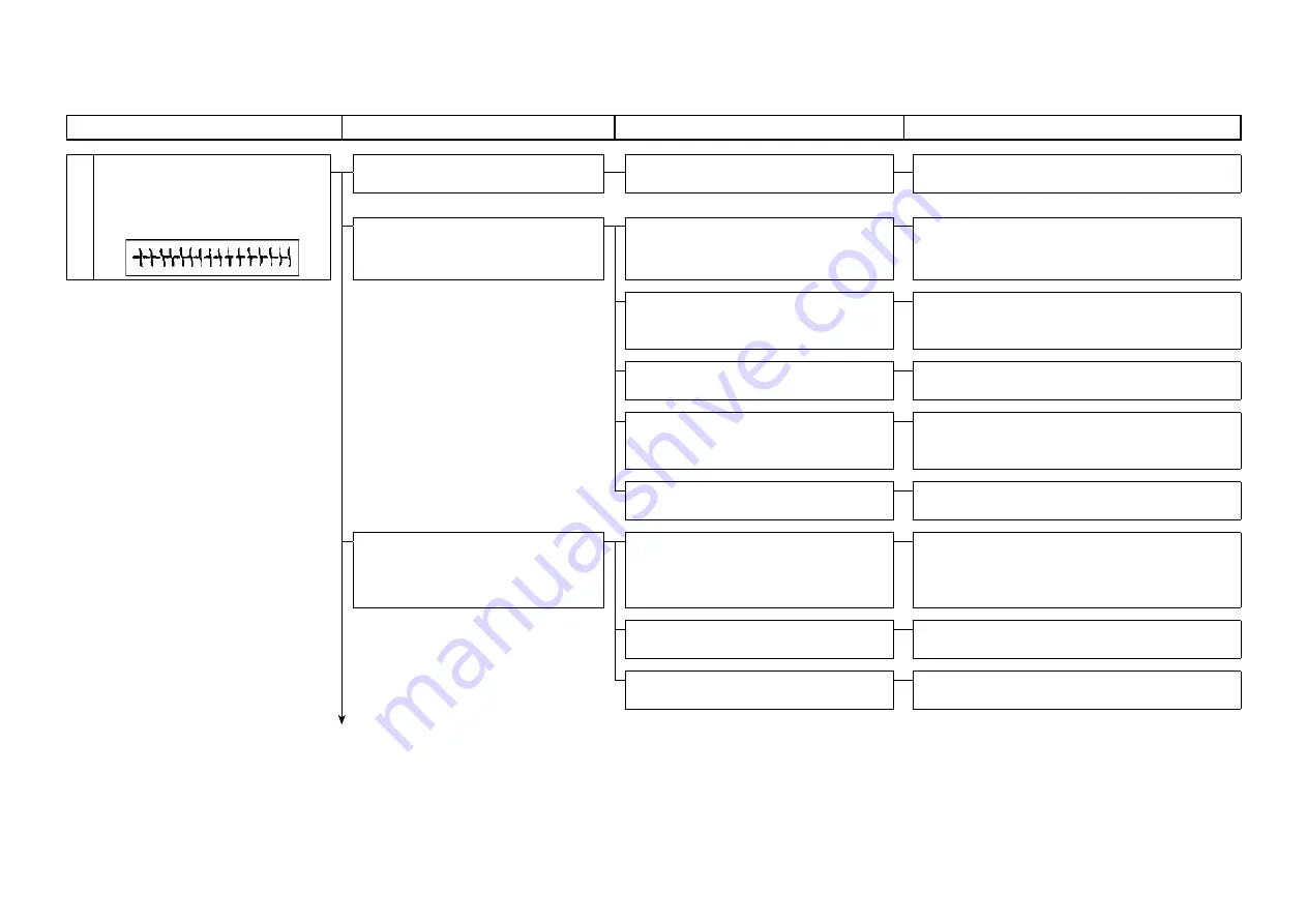
1. Puckering

Wrinkles developed around 

stitches due to stitch shrinkage or 

uneven material feed.

1-1) The needle is too thick.

1-A) Deformation of clothes by pene-

trating a needle into cloth

Use a thin needle as much as possible. Use a 

KN or SF needle (standard needle).

1-2) Thread tension (top or bot-

tom) is too high.

2-A) The thread path is not smooth.

Finish the thread path appropriately.

2-B) The timing of the hook is too 

late.

Hasten the timing of the hook without oc-

currence of stitch skipping to obtain smooth 

unthreading.

2-C) The feed timing is too fast.

Delay the feed timing compared to the needle 

timing to reduce feeding.

2-D) The stroke of the thread take-

up lever is too long.

Move the arm thread guide rightward to reduce 

the thread feeding with the thread take-up 

lever.

2-E) The stroke of the thread take-

up spring is too short.

Increase the stroke.

1-3) Pressing is inappropriate.

3-A) The pressure is too high.

Minimize the pressure. For some materials, 

sewing with the presser slightly floated with the 

adjustable screw of the minute presser lifter is 

effective. 

3-B)

The finish of the backside of the 

presser is rough.

Use a buff or the like to smooth the presser.

3-C)

The material is difficult to feed.

Use a fluorocarbon resin presser or a special 

processed presser.


To the next page

(2) Sewing performance

Содержание DDL-8000A

Страница 1: ...40218604 No E440 00 ENGINEER S MANUAL DDL 8000A Direct drive High speed Automatic Thread Trimmer ...

Страница 2: ... information which are not covered in the Instruction Manual When carrying out the maintenance work on the sewing machine be sure to refer also to the Instruction Manual and the Parts List Further refer to Engineer s Manual In addition for the motor for the sewing machine with thread trimmer refer to the separate Instruction Manual or This manual gives the Standard Adjustment on the former page un...

Страница 3: ... needle changing bobbin changing or oiling and cleaning Electrical shock danger label DANGER This indication is given where there is an immediate danger of death or serous injury if the person in charge or any third party mishandles the machine or does not avoid the dangerous situation when operating or maintaining the machine WARNING This indication is given where there is a potentiality for deat...

Страница 4: ...o be used only by the operator who has been trained educated by the employer with respect to the machine oper ation and how to operate the machine with safety to acquire adequate knowledge and operation skill To ensure the above the employer has to establish an education training plan for the operators and edu cate train them beforehand Items for which the power to the machine has to be turned off...

Страница 5: ...sed by earth leakage or dielectric strength voltage fault In addition be sure to connect the power plug to the grounded outlet without exceptions 2 Be sure to ground the earth cable in order to prevent accident caused by earth leakage IV Motor 1 Be sure to use the specified rated motor JUKI genuine product in order to prevent accident caused by burnout 2 If a commercially available clutch motor is...

Страница 6: ...reful 7 If the machine cannot be normally operated after repair or adjustment immediately stop operation and contact JUKI or the distributor in your area for repair in order to prevent accident that can result in per sonal injury or death 8 If the fuse has blown be sure to turn the power off and eliminate the cause of blowing of the fuse and replace the blown fuse with a new one in order to preven...

Страница 7: ...that some parts have been factory insulated with tubes or tapes or floated above the PWB for safety s sake In addition internal wiring has been factory routed or clamped in such a way that it does not come close to high voltage parts Be sure to re place those parts as they are at the time of delivery 7 Be sure to use JUKI genuine parts when replacing any of the machine parts JUKI assumes no respon...

Страница 8: ...in a stable state in order to protect against accident that can result in personal injury In addition be sure to select appropriate tools 5 In prevention of accident that can result in personal injury be sure to tighten screws and nuts in assem bly work with a specified torque if specified or with an appropriate torque if not specified After the completion of assembly work be sure to check that sc...

Страница 9: ...prevent possible injury to hands be sure to keep your hands away from the vicinity of the hook during oper ation In addition be sure to turn OFF the power to the machine when replacing the bobbin 6 So as to avoid personal injuries caused by abrupt start of the machine turn OFF the power switch and ascertain that the sewing machine does not run even if the starting pedal is de pressed when performi...

Страница 10: ...t of the sewing machine from the power supply Selection of the power switch EU type Be sure to use the IEC60204 1 compli ant power switch with rated current of 20A or more and short circuit breaking capacity of 120 A or more Warning label against pinching This label warns thar fingers or other parts of human body can be pinched in the thread take up lever Thread take up lever cover This is a cover...

Страница 11: ...verse feed stitch length check manual 31 3 Reverse feed stitch length check electrically operated 31 4 Adjustment of normal reverse stitching 33 5 Adjustment of feed 0 33 6 Adjustment of ffeed dial section 35 7 Installation of the reverse feed arm and the reverse feed solenoid 37 10 Adjusting the needle thread presser device 39 1 Needle thread presser device 39 2 Adjusting the remaining length of ...

Страница 12: ...or function 86 7 List key input functions at power on 88 5 Function setting list 89 1 Function setting list 89 2 Further information aboout memory switch 95 3 List of error code 103 6 Electrical component and the like 105 1 Control Box 105 2 Panel 106 7 Maintenance 107 1 Oil quantity check 107 2 Cleaning 107 3 Application of appropriate grease 109 1 Grease up warning and grease up error 109 2 Need...

Страница 13: ...xi 10 Screws for attachment and positions of external parts 134 11 Troubles and corrective measures 135 1 Mechanical components 135 2 Sewing performance 149 12 Block diagram 158 13 Drawing of table 159 ...

Страница 14: ...Nm65 to 110 DP 5 21 20 to 23 134 Nm130 Nm125 to 160 DP 5 21 20 to 23 134 Nm130 Nm125 to 160 18 Dimensions From needle to ma chine arm width 303mm From needle to ma chine arm high 137mm Bed size 178mm 517mm 19 Machine head drive Compact AC servomotor 550W that is directly connected to the main shaft direct drive system 20 Machine head weight 40 2kg 21 Power consumption 330VA 22 Working temperature ...

Страница 15: ... 23 134 Nm130 Nm125 to 160 DP 5 21 20 to 23 134 Nm130 Nm125 to 160 18 Dimensions From needle to ma chine arm width 303mm From needle to ma chine arm high 137mm Bed size 178mm 517mm 19 Machine head drive Compact AC servomotor 550W that is directly connected to the main shaft direct drive system 20 Machine head weight 40 2kg 21 Power consumption 330VA 22 Working temperature and humidity Temperature ...

Страница 16: ... switch Take up lever cover Thread stand Finger guard Operation pedal Under cover LED hand light 2nd thread tension One touch type reverse feed button Power switch For CE Needle thread presser device Pedal sensor Bobbin winder unit USB terminal 1st thread tension USB terminal Oil filler port ...

Страница 17: ...Its brightness can be adjusted with the hand switch It should be adjusted to match the sewing item and or to your preference One touch type reverse feed button This button allows users to conduct reverse stitching Needle thread presser device This device is able to tuck the needle thread on the wrong side of material under control of the signal from the control box Bobbin winder unit This unit is ...

Страница 18: ...stment Shipped feed dog 40133950 MS 11403003 SH AA BB 11062601 SH GG Engraved marker dot position on the horizontal feed bar shaft a b A B a b a b A B DDL 8000A MS 0 8mm DDL 8000A SH DDL 8000 SJ 1 2mm Standard feed dog height Feed dial graduation 0 0 8mm DDL 8000A MS 1 2mm DDL 8000A SH DDL 8000A SJ Standard feed dog gradient The engraved marker dot on the feed bar shaft is adjusted by a feed dog o...

Страница 19: ...r bar perpendicular to the vertical feed bracket shaft and horizontal feed bracket shaft without load If the gradient of the feed dog is adjusted for either shaft only the feed dog height may be changed Adjustments are need ed for both shafts in all cases According to the shaft adjusting position the position of feed dog motion may be shifted In such a case loosen the tighten ing screw of the hori...

Страница 20: ...ook WARNING Be sure to turn the power OFF before the following work in order to prevent personal injury due to unintentional starting of the sewing machine Standard adjustment C D A B B 0 04 to 0 1mm A Lubricated hook K Part No 23621303 ...

Страница 21: ...ook Since then firmly tighten the three hook setscrews Dry hook Use the following part number The hook part numbers come in two types according to the specifi cations 22890206 without the needle guard 22890404 with the needle guard 22890305 22890206 with special surface treatment Caution The dry hook RP hook tends to collect thread chips and material dust This can cause malfunction or de fective s...

Страница 22: ...er line position 0 1 mm Standard Adjustment DDL 8000A MS DDL 8000A SH DDL 8000A SJ Needle and feed timing Models DDL 8000A MS DDL 8000A SH DDL 8000A SJ Vertical feed cam engraved marker line 0 20 Feed dial graduations 3 4 Needle and feed timing In a moment when the feed dog is positioned below the upper surface of the throat plate the upper end lower end of the throat plate for B SH of the needle ...

Страница 23: ...n until the upper end of the needle hole coincides with the upper plane of the throat plate In case of other than the DDL 8000A MS the engraved marker dot of the pulley cover is matched with the engraved marker dot between the two engraved lines of the flywheel When the top end of the needle hole is matched with the top face of the throat plate tighten two lower sprocket screws Tightening torque f...

Страница 24: ... sure to turn the power OFF before the following work in order to prevent personal injury due to unintentional starting of the sewing machine Standard adjustment 2 Feed trace and phase adjustment 1 Timing standard 2 Timing fast 3 Timing slow ...

Страница 25: ...nd the plus side the vertical feed timing is delayed against horizontal feed Also delayed against the needle Cautions Adjustments should be done within 20 2 gradua tions Cautions 1 When timing of the vertical feed cam is changed the feed timing is also changed against the needle 2 The angle of the engraved marker line gradua tion 1 denotes 10 When tightening the two set screws of the vertical feed...

Страница 26: ... turn the power OFF before the following work in order to prevent personal injury due to unintentional starting of the sewing machine Standard adjustment A B C C Height of the presser adjusting screw can be read from the upper face value of the nut Example Approx 40mm ...

Страница 27: ...in Direction A for strengthening Turning in Direction B for weakening 2 Tighten the nut after adjustments Standard value of the presser adjusting screw height C Specifications Height mm 🅒 Presser Pressure N Presser Pressure kg DDL 8000A MS 29 5 39 2 4 DDL 8000A SH DDL 8000A SJ 29 5 60 6 1 The presser adjusting screw varies depending on the specification ...

Страница 28: ...in order to prevent personal injury due to unintentional starting of the sewing machine Standard adjustment 1 Bobbin case with idling prevention spring Drawing is for 40000264 B A C For the bobbin case with idling prevention spring 1 2 3 4 Ear 0 3 0 2mm Bobbin revolution Change the height ...

Страница 29: ...pring tension When the bobbin runs idle Increase the tension of the idle prevention spring When the thread is not well tightened Decrease the tension of the idle prevention spring Adjustment of idling prevention spring tension If there is a problem of bobbin idling or uneven sewing at high or low speed use of a bobbin case with an idling prevention spring is effective 1 Insert an old needle as ill...

Страница 30: ...ard adjustment Inner hook presser position Needle entry About the standard part numbers Inner hook As seen from above after removing the throat plate Part name MS type Semi dry SH SJ type Micro quantity lubrication Inner hook presser 40089607 40089610 Convexity of metal A from machined surface Convexity of Hook shaft B 1 8 9 9 Plunger position Hook shaft end Hook shaft position A B Reference hole ...

Страница 31: ... center of the convex section of the inner hook presser Caution When adjusting the hook shaft position make sure of the plunger movement without fail the bobbing mo tion If the convex section of the inner hook presser has any flaw this can be a cause of thread breakage or uneven sewing In such a case the damaged part shall be replaced with a new one If the inner hook presser is positioned inadequa...

Страница 32: ... to turn the power OFF before the following work in order to prevent personal injury due to unintentional starting of the sewing machine Standard adjustment 1 Method of lubrication SH SJ type Micro quantity lubrication MS type Semi dry ...

Страница 33: ...er pump Quantity of oil can be adjusted by the hook oil adjusting screw Lubricant can be fed to the oil tank through the arm lubrication hole 2 MS type Specification for semi dry items Face plate needle bar lubrication Lubrication by grease sealed in the needle bar lower metal Hook Forced lubrication by the plunger pump Quantity of oil can be adjusted by the hook oil adjusting screw Lubricant can ...

Страница 34: ...wer OFF before the following work in order to prevent personal injury due to unintentional starting of the sewing machine Standard adjustment 2 Method of lubrication to the oil tank 3 Method of oil drainage from the oil tank Engraved marker line MAX ...

Страница 35: ...and an alarm sounds Supply oil Cautions 1 When you use a new sewing machine or a sewing machine after an extended period of disuse use the sewing machine after performing break in at 2 000 sti min or less 2 For the oil for hook lubrication purchase JUKI NEW DEFRIX OIL No 1 part number 40214221 MDFRX1600C0 or JUKI CORPORATION GENUINE OIL 7 part number 40102087 3 Be sure to lubricate clean oil 4 Do ...

Страница 36: ...brication WARNING Be sure to turn the power OFF before the following work in order to prevent personal injury due to unintentional starting of the sewing machine Standard adjustment 4 Cleaning of the oil filter ...

Страница 37: ...ery three months 1 Let the sewing machine fall down 2 Remove the pipe stop and then the thread waste attached to the oil filter Cautions Be careful that a lubrication pipe and so on are not damaged at the time of maintenance of a filter If there is clogging in the oil filter smooth lubrication cannot be main tained from the lubrication hole ...

Страница 38: ...aper Approx 70mm Approx 25mm To be applied to the bed wall Hook Lower shaft front metal Bed Oil trace checking paper Apply the oil quantity trace checking paper to hooks lower side and check it from a distance of 3 to 10mm 3 to 10mm Oil quantity small Oil quantity large Oil sprinkles from the hook DDL 8000A MS 0 5 to 1mm DDL 8000A SH SJ 1 to 3mm 8000A MS 1 to 1 5mm 8000A SH SJ 2 to 4mm Oil sprinkl...

Страница 39: ...ing seizure Therefore use the machine after running in operation at 2 000sti min or below 7 Essentials for hook oil adjustments 1 When the quantity of hook oil is adjusted from excessive oiling condition to reducing condition loosening the screw it is possible to carry out stable adjustments 2 Check the oil quantity about three times to confirm the stability 3 If the quantity of oil is too much be...

Страница 40: ...work in order to prevent personal injury due to unintentional starting of the sewing machine Standard adjustment If the cam roller is raised the problem that the presser foot sole fails to come in contact with the throat plate can occur Light contact state Engraved line 🅐 0 3 mm feeler Engraved line 🅑 Engraved line 🅐 ...

Страница 41: ...e power loosen the setscrew on the sensor mounting plate and adjust the position of the sensor mounting plate To increase the presser rising amount move it to the A side To decrease the presser rising amount move it to the B side 3 Tighten the setscrew on the sensor mounting plate 4 Turn on the power again and depress the back part of the pedal to the 1st step to lift the presser foot 5 Make sure ...

Страница 42: ... Neutral Presser foot 1st step lifting position Presser foot lifting position when the sewing machine is stopped during sewing Presser position after depressing the back part of the pedal to the 2nd step and trimming the thread Presser foot 2nd step lifting position Presser lifter at depressing the back part of the pedal to the 2nd step position thread trimmer again after completion of thread trim...

Страница 43: ...arch operation After the power is turned on conduct origin search and move it to the presser foot 1st step lifting position or presser foot 2nd step lifting position when depressing the back part of the pedal to the 1st or 2nd step the first time ...

Страница 44: ... OFF before the following work in order to prevent personal injury due to unintentional starting of the sewing machine Standard adjustment 1 Adjustment of forward feed stitch length 2 Reverse feed stitch length check manual 3 Reverse feed stitch length check electrically operated ...

Страница 45: ...gh turn the feed adjust dial while pressing the feed adjust stopper in the direction of the arrow 🅑 arm rear side 4 When the feed adjust stopper is released the feed adjust dial is fixed 2 Reverse feed stitch length check manual 1 Turn the feed adjust dial in the direction of the arrow so that the required figure is adjusted to the engraved marker dot 🅐 of the arm 2 Reverse feed takes place when t...

Страница 46: ...he power OFF before the following work in order to prevent personal injury due to unintentional starting of the sewing machine Standard adjustment 4 Adjustment of normal reverse stitching 5 Adjustment of Feed 0 Method by removing the gear box cover standard adjustment ...

Страница 47: ...3 Loosen three setscrews of the auto reverse feed solenoid and remove this auto reverse feed solenoid 4 Loosen the feed changing arm B setscrew 5 Adjust the feed adjusting link A and the feed adjusting link B so that they are aligned in a straight line Tighten them with the feed changing arm B setscrew 6 Pinch a piece of paper beneath the presser hardware and turn the flywheel by hand in forward d...

Страница 48: ...onal starting of the sewing machine Standard adjustment 6 Adjustment of the feed dial section Feed dial graduation Armʼs engraved marker dot Grooves of the feed adjust dial Engage the convex tip of the feed regulator pin with the grooves of the feed adjust dial Convex tip of the feed regulator pin Part Configuration Diagram of the feed dial mechanism Type II ...

Страница 49: ...g front 5 Set the larger diameter side of the feed regulator spring to the arm side and attach the feed regulator stopper by en gaging the small hole with the convex tip of the feed regulator pin Also make sure to engage the convex tip of the feed regulator pin with the grooves of the feed adjust dial Feed dial of respective spcefications Specifications Part No Maximum graduation DDL 8000A MS SH 4...

Страница 50: ...NG Be sure to turn the power OFF before the following work in order to prevent personal injury due to unintentional starting of the sewing machine Standard adjustment 7 Installation of the reverse feed arm and the reverse feed solenoid 0 5 to 1 0mm ...

Страница 51: ...everse feed arm so that the gap length becomes 0 5 to 1 0mm between the rubber sea and the reverse feed solenoid when the reverse feed lever is pulled to its limit position In the position where the reverse feed link is positioned in the center of the reverse feed plunger groove tighten the reverse feed arm setscrew 5 If the motion of the reverse feed plunger is not smooth this may result from the...

Страница 52: ...le thread presser device WARNING Be sure to turn the power OFF before the following work in order to prevent personal injury due to unintentional starting of the sewing machine Standard adjustment 1 Needle thread presser device ...

Страница 53: ...d reducing the needle thread supply from the thread take up it is possible to lessen so called bird s nest phenomenon of the cloth lining Operability around the needle entry point is improved Applicability of various kinds of attachments designed for use around the needle entry point is im proved How to set the needle thread presser device Keep thread presser operation enable disable switch held p...

Страница 54: ...wer OFF before the following work in order to prevent personal injury due to unintentional starting of the sewing machine Standard adjustment 2 Adjusting the remaining length of needle thread 3 Length of needle thread remaining at the needle A B MS type SH SJ type c c c 35 to 45mm ...

Страница 55: ... trimming or counterclockwise in direction B to lengthen the thread length 3 Length of needle thread remaining at the needle The needle thread length C dimensions of the S type and H type is 35 to 45mm So called bird s nest phenomenon is reduced by shortening the length of needle thread remain ing at the needle In this case however the needle thread is likely to slip off the needle eyelet To reduc...

Страница 56: ...er device WARNING Be sure to turn the power OFF before the following work in order to prevent personal injury due to unintentional starting of the sewing machine Standard adjustment 4 Response to problems occurring at the beginning of sewing ...

Страница 57: ...djust the presser foot pressure and the sewing speed appro priately to prevent insufficient feed efficiency due to jumping or other faults of the presser foot Confirm the adjustment result by actually sewing the material 1 Press 2 Press the switch to select the item number in the table 3 Press the switch to activate the setting section and press the switch to adjust the value 4 Press the switch to...

Страница 58: ...injury due to unintentional starting of the sewing machine Standard adjustment 1 Adjustment of the thread trimming cam position 2 Adjustment of the thread trimming link stopper screw G 2mm 16 5mm The screw tip is flat Thread trimming link stopper setscrew B Thread trimming link stopper setscrew A The screw tip is pointed Inside Outside ...

Страница 59: ...d trimming link stopper setscrew B that is locking the thread trimming link stopper setscrew A 3 Adjust the thread trimming link stopper setscrew A to make the clearance to be uniform between the thread trimming roller and the thread trimming cam groove on both inside and outside 4 Tighten the thread trimming link stopper setscrew B In this case make sure that the thread trimming link stopper sets...

Страница 60: ... of the sewing machine Standard adjustment 3 Thread trimming cam timing Turn thread trimming cam in the direction of arrow until the outer periphery of thread trimming cam groove C comes in contact with roller and stops At this position fix thread trimming cam setscrew Illustration as observed from D right side face C C C Correct F Wrong G 🅐 Marking point Engraved line E ...

Страница 61: ...rews No 1 and No 2 of thread trimming cam set screw in the written order 3 Match the engraved line A on the control box with the colorless engraved line on the hard wheel and the enter of the colorless engraved dot 4 Pressing cam follower to the left in the direction of arrow E engage thread trimming cam with roller Then turn only thread trimming cam with fingers in the direction which is opposite...

Страница 62: ... needle A to the tip of the thread spreading knife 5 5 to 6 5mm Fig 1 Standby state of the knife A The position of the thread spreading knife and needle Fig 1 a The thread trimming shaft and the thread trimming drive arm Fig 1 b A Far end of the hole in loop spreading knife aligns with the tip of thread trimming knife Fig 2 Aligning state of salient portion of loop spreading knife and thread trimm...

Страница 63: ...There is seldom an actual margin of adjustment because it is used for the creak of the Phillips head screw 5 The amount of engagement between loop spreading knife and thread trimming knife is S type 2 0 2 5 mm H type 2 5 to 3 0 mm as measured from center of needle A Refer to Fig 3 Be aware that if the distance be tween loop spreading knife and center of needle A is reduced thread loop is likely to...

Страница 64: ...jury due to unintentional starting of the sewing machine Standard adjustment 4 Adjusting the knife unit 2 Adjustment of the knife unit 5 Adjustment of thread trimming speed Memory switch No Item Setting range Initial value Unit P49 Thread trimming sewing speed 100 to 500 210 sti min P50 Second thread trimming speed 0 to 500 180 sti min A ...

Страница 65: ... The thread trimming speed has been adjusted to 210 sti min and the second thread trimming speed has been adjusted to 180 sti min at the time of shipment Depending on the type of thread to be used the thread trimming speed should be increased On the other hand in the case of using fragile thread such as a high count filament type thread or cotton thread the thread trimming speed should be decrease...

Страница 66: ...t WARNING Be sure to turn the power OFF before the following work in order to prevent personal injury due to unintentional starting of the sewing machine Standard adjustment 6 Adjustment of rise of the second thread tension disc 1 0 to 1 5 mm ...

Страница 67: ...se of the second thread tension disc When increasing the amount of rise Loosen the thread tension release wire fixing screw and move the thread tension release wire to the right When decreasing the amount of rise Loosen the thread tension release wire fixing screw and move the thread tension release wire to the left Caution After adjustments tighten the thread tension release wire fixing screw ass...

Страница 68: ...d trimming unit WARNING Be sure to turn the power OFF before the following work in order to prevent personal injury due to unintentional starting of the sewing machine Standard adjustment 7 Adjustment of the driven part stopper ...

Страница 69: ...roblem such as a service interruption occurs 1 In the state that the thread trimming device is not in action adjust two driven part stopper setscrews so that the gap length be comes 0 3mm between the notch of the camʼs driven part and the camʼs driven part stopper 2 Adjust two driven part stopper setscrews so that the gap length becomes 1mm between the notch of the camʼs driven part and the camʼs ...

Страница 70: ...ng work in order to prevent personal injury due to unintentional starting of the sewing machine Standard adjustment 8 Replacement of the knife unit Ⓐ Ⓐ No 3 No 4 No 1 No 6 No 5 Knife unit Part No Handling device knife Part No Thread trimmer knife Part No DDL 8000A MS SH SJ 40211087 40195289 40195552 ...

Страница 71: ...e unit Method of replacement 1 Let the sewing machine fall down 2 Remove the needle hook and the inner hook presser 3 Remove the moving knife link stepped screw Apply the LOCKTITE 243 on a screw at the time of recombination 4 Remove the C ring 5 Remove the female unit from the metal ...

Страница 72: ...stance from the left end of the thread spreading knife tip to the left end of the thread spreading plate shall be 0 to 0 5 mm The position of the thread spreading plate shall be on the rear side of the thread spreading knife When the thread spreading knife is moved to the maximum forward position the tip of the thread spreading plate shall not interfere with the thread spreading knife Largest diam...

Страница 73: ...he thread spreader shall be in the range between 0 mm and 0 5 mm 3 Make sure that there is no interference by rotating the hook Make sure that the thread spreading knife enters between the thread trimming knife and the thread spreader by rotating the thread spreading knife Caution 1 The outer periphery of the hook is not uniform So adjust at the smallest clearance position 2 When making an adjustm...

Страница 74: ...f the sewing machine Standard adjustment 11 Installation position of the thread trimming shaft 10 Installed length of the thread trimmer connector bar asm 102 0 2mm Reference value 40mm Connecting rod asm Part No Connecting rod asm dimension DDL 8000A MS SH SJ 40174323 102 0 2mm Thread trimming shaft The edge of the thread trimming shaft is matched with the edge of the bed ...

Страница 75: ...or bar asm 40174323 without drawing out the lower shaft When the nuts are loosened the respective subsidiary parts are disas sembled and the thread trimmer connector bar can be taken out 4 After disassembly reassemble the parts so that the standard adjusting values can be secured 11 Installation position of the thread trimming shaft Install the thread trimming shaft in the position so that the edg...

Страница 76: ...l parts WARNING Be sure to turn the power OFF before the following work in order to prevent personal injury due to unintentional starting of the sewing machine Standard adjustment 1 How to remove the control box 1 2 3 4 Rear cover ...

Страница 77: ...move the earth cable connected to the head If the screwdriver tip is not inserted fully in the slot the flange part of the upper sprocket is deformed or destroyed 4 Remove the setscrews and from the control box Screw part number SL4052591SC L 25 SL4051691SC L 16 5 Assembly can be conducted by the reversed procedure Cautions Pay attention not to catch cords at the installation of the control box ...

Страница 78: ... external parts WARNING Be sure to turn the power OFF before the following work in order to prevent personal injury due to unintentional starting of the sewing machine Standard adjustment 2 Clearance of the hand wheel 1mm ...

Страница 79: ... 2 Clearance of the hand wheel 1 The clearance between the hand wheel and control box is 1 mm For adjustments loosen the hand wheel setscrews 2 pcs If a clearance is too much this can be a possible cause of entangle ment of the thread from the thread stand ...

Страница 80: ...following work in order to prevent personal injury due to unintentional starting of the sewing machine Standard adjustment 3 Adjustment of the bobbin winder unit 14 mm Operator side In the state of OFF the standard distance of the bobbin winder lever is 14mm from the bobbin winder shaft ...

Страница 81: ...ion 1 Remove the window plate from the rear side of the arm 2 Loosen the bobbin winder driver wheel setscrews 2 pcs of the bobbin winder driver wheel 3 Mount the bobbin winder unit on the arm 4 Turn ON the bobbin winder lever and let the head coincide with the bobbin winder lever At that time the head of the bobbin winder unit setscrew shall be made to coincide with the bobbin winder lever 5 Light...

Страница 82: ...injury due to unintentional starting of the sewing machine Standard adjustment 14 Replacement of the timing belt WARNING Be sure to turn the power OFF before the following work in order to prevent personal injury due to unintentional starting of the sewing machine Standard adjustment Timing belt Second screw First screw Hand wheel ...

Страница 83: ...tall a new motor in the mounting position in correct revolving direction Description Part No Motor 40211082 Coupling asm 40172398 9 In the procedures below reassembly can be carried out in the reverse order for disassembly If no clearance is secured this can be a cause of motor bearing destruction After disassembly reproducibility will be lost Adjustment Procedure Results of Improper Adjustment Th...

Страница 84: ...hanism configuration and adjustments WARNING Be sure to turn the power OFF before the following work in order to prevent personal injury due to unintentional starting of the sewing machine Standard adjustment 1 Configuration ...

Страница 85: ... Improper Adjustment 1 Configuration Oil quantity sensor The oil quantity sensor that detects the oil amount is installed inside the oil tank Refer to 3 15 2 Procedure of attaching and detaching for how to replace the oil quantity sensor ...

Страница 86: ...ork in order to prevent personal injury due to unintentional starting of the sewing machine Standard adjustment 2 Procedure of attaching and detaching Remove the connector pin of the oil quantity sensor Remove the three setscrews from the oil tank Oil quantity sensor Position of connector pin No 4 Red No 9 Black No 10 Yellow ...

Страница 87: ...rting of the sewing machine Standard adjustment Remove the nut from the oil quantity sensor and the oil tank lid and then remove the oil quantity sensor Installation can be conducted by the reversed procedure Put the O ring put the packing between the oil tank and oil tank lid and fully tighten the oil quantity sensor nut and oil tank lid Caution Make sure that there is no tilt clearance ...

Страница 88: ...r to prevent personal injury due to unintentional starting of the sewing machine 1 Remove the rear cover six setscrews of the cover 2 Remove a cable clip band and lay the panel cable into the arm 3 Loosen the panel setscrew Two setscrews for the upper arm and one setscrew for the lower arm Rear cover ...

Страница 89: ... reassemble it ac cording to the opposite procedure Caution Pull the panel cable If it is loose it may interfere with the upper shaft and the like Secure the laid cable with a cable clip band If a cable clip band is not available right now refer to When a cable clip band is not available right now on the next page for a provisional means Completion ...

Страница 90: ...panel cable not to it in the arm 2 Lay the redundant part of the cable under the cable coming out from the panel 3 Put the protruding cable into the hole of the side plate Do not slack the cable Lay the cable under this cable Put the cable into the hole of the side plate ...

Страница 91: ... 78 ...

Страница 92: ...justment of thrust values of an upper shaft WARNING Be sure to turn the power OFF before the following work in order to prevent personal injury due to unintentional starting of the sewing machine Standard adjustment ...

Страница 93: ...A If the screwdriver tip is not inserted fully in the slot the flange part of the upper sprocket is deformed or destroyed 4 Lightly turn the screwdriver to move the coupling toward B in the direction of the arrow The torque to turn the screwdriver is 7kgf cm Light turning is sufficient If it is turned too strong the flange part of the upper sprocket is deformed or destroyed 5 Tighten the setscrew ...

Страница 94: ...f stopping the sewing machine between up and down Short time Used to set the type of stitching to free stitching Long time Used to change over the thread trimming operation between enable disable Short time Used to set the type of stitching to overlapped stitching Long time Used to change over the lifting of the presser foot during sewing between automatically lift not lift Short time Used to carr...

Страница 95: ...n functions to the function keys Long time Assign the function to the function key F1 Refer to Function keys F1 and F2 setting in the Instruction Manual for how to assign functions Short time Used to display the parameters registered to function key F2 There is no default setting Before use of this assign functions to the function keys Long timee Used to register a parameter to function key F2 Ref...

Страница 96: ...e function setting No P86 that is used for setting the number stitches to be sewn using the soft start function 3 Press to flash setting No B on and off In this state change the set value by pressing 4 Press to determine the set value 5 Press to return the sewing machine to the normal sewing state In the case of changing the set value for other function setting number repeat the steps of procedure...

Страница 97: ...case the control box is replaced or in any case where it is necessary 4 Adjusting the main shaft stop position Memory switch No P72 1 Activate the memory switch in the service level Refer to 4 2 2 Service level 2 Press to flash function setting No A on and off In this state press to select parameter P72 3 Turn handwheel in the normal direction of rotation to align marker line 🅐on the electrical bo...

Страница 98: ... to determine the password and press to return the normal sewing state 5 If the password is other than 0000 trying the activation of the memory switch displays the password input screen before the function setting screen is displayed 6 Enter the four digit password you have set to the function setting No J14 using and 7 The function setting screen is displayed by pressing On this screen the functi...

Страница 99: ...lue of the supply voltage N14 ST software version U Displays the version of the presser lifter motor control software N15 Grease up stich count S Displays the number of stiches when greasing is necessary The counter can be cleared 1 Check of software version 1 Activate the memory switch in the user level Refer to 4 2 1 User level 2 Press in the state that the function setting No A is blinking to s...

Страница 100: ...e grease E220 Grease shortage warning error is displayed for three seconds after turning the power ON In this state however the sewing machine can be used for a certain period time Cautions Once E220 error is displayed be sure to replenish the sewing machine with grease without exceptions To clear the error refer to 4 3 3 1 How to cancel grease up error Grease shortage error If the error E220 is n...

Страница 101: ...input functions at power on Turning on the power while the panel switch on the front is pressed allows each function to be set Function key Memory switch Service level Password clear Panel software rewrite Only 8000AS AB ...

Страница 102: ...hangeover of the reverse feed stitching at the start of sewing between Auto Manual The sewing speed for the reverse feed stitching at the beginning of sewing is set with this function setting item 0 The reverse feed stitching is performed by manually operating the pedal 1 The reverse feed stitching is performed at the sewing speed set with P04 Reverse feed stitching speed at the beginning of sewin...

Страница 103: ...nction setting item for preventing the sewing machine from overrunning before stopping on the way 1 to 45 S 16 P45 Setting of BT holding Duty Sets the current value of the solenoid at BT on 1 to 50 S 30 P46 Setting of the function of reverse revolution to lift the needle This function rotates the main shaft in the reverse direction of sewing to bring the needle bar to the highest position ON Rever...

Страница 104: ...read trimming solenoid is turned OFF 0 to 500 ms S 250 P112 Needle up stop angle The angle from the upper dead point of needle to the needle up stop position is set with this function setting item 359 to 359 S 55 P113 Bobbin counter The largest value that the bobbin counter can count is set with this function setting item When the counter reaches that value it stops counting 0 to 9999 10 stitches ...

Страница 105: ...ctivated If this function is activated the function of P142 cannot be used 0 to 1 U 0 P140 Number of stitches of reverse feed stitching on the way The number of stitches of reverse feed stitching on the way is set with this function setting item 1 to 19 stitches U 4 P141 Condition to be satisfied to enable the reverse feed stitching on the way while the sewing machine is at rest The condition to b...

Страница 106: ...thread is held Setting of presser lifting amount at holding thread 0 to 359 U 100 P163 Ending angle of soft start for the thread clamp The ending angle of the soft start for the thread clamp is set with this function setting item 0 to 720 U 340 P164 Setting of presser lifting amount at holding thread The amount of lift of the presser foot when clamping the thread is set with this function setting ...

Страница 107: ... Sewing machine monitoring items No Item Description Setting range Setting level Default N01 Main software version Displays the main software version U N02 Panel software version Displays the panel software version U N03 Sewing machine speed monitor Measures the sewing machine speed and displays it S N04 Input value of pedal A D Displays the input value of pedal A D S N05 Display of principal axis...

Страница 108: ... sewing Function setting No P13 This function temporarily stops the sewing machine even when keeping depressing the front part of the pedal at the time of completion of process of reverse feed stitching at the start of sewing It is used when sewing a short length by reverse feed stitching at the start of sewing P 1 3 CON Not provided with the function of temporary stop of the sewing machine immedi...

Страница 109: ...stitches for Section A before selecting for B A B Start point A A B B Start point Start point A B Start point Case 1 Longer A and shorter B Adjustment P18 Decrease the set value A becomes shorter and B becomes longer Case 2 Shorter A and longer B Adjustment P18 Increase the set value A becomes longer and B becomes shorter Case 3 Normal A and longer B Adjustment P19 Decrease the set value B becomes...

Страница 110: ...D D Start point Start point Case 6 Normal C and shorter D Adjustment P25 Increase the set value C becomes shorter and D becomes longer Case 5 Normal C and longer D Adjustment P25 Decrease the set value C becomes longer and D becomes shorter Case 4 C is short Adjustment P77 Increase the set value C becomes longer Case 3 C is longer Adjustment P77 Change the set value to such a value that shortens C...

Страница 111: ...omes longer Reverse revolution to lift the needle after thread trimming Function setting No P46 This function is used to make the sewing machine rotate in the reverse direction after thread trimming to lift the needle bar almost to highest position Use this function when the needle appears under the presser foot and it is likely to make scratches on the sewing products of heavy weight material or ...

Страница 112: ...No P136 The needle bar goes up to its upper position and the presser motor carries out origin retrieval operation immediately after the power is turned ON 1 3 6 0 Neither the needle bar nor the presser motor Operates when the back part of pedal is depressed 1 Needle bar goes up to its upper position and the presser motor automatically goes up after automatic origin retrieval 2 Needle bar automatic...

Страница 113: ...e function setting No 140 can be performed 1 1 0 When operating touch back switch at the time of either stop of the sewing machine or depressing front part of the pedal reverse feed stitching as many as the number of stitches specified by the function setting No 140 can be performed 1 0 1 When operating touch back switch at the time of depressing front part of the pedal automatic thread trimming i...

Страница 114: ...art end angle 340 degrees 300 degrees 340 degrees 100 degrees P161 ON OFF P167 Duty 69 P37 Duty MS 40 SH 50 P166 Duty switching time 7 ms P167 Duty switching time 7 ms P78 Thread presser start angle 190 degrees P79 Thread presser end angle 300 degrees P165 Presser lifting time when the thread presser is used 20 ms P162 Presser lifting start angle when the thread presser is used 100 degrees P164 Pr...

Страница 115: ...activated Apply brake at P170 Duty for P75 time after passage of P74 time ON HEDA_PWM REVERSE Name of signal OFF ON OFF No 168 No 169 No 76 No 150 No 75 No 74 Duty No 149 Duty No 45 Duty No 170 If the memory switch described above is changed multi layer stitches of automatic reverse are not matched each other and therefore change in the initial position of the automatic reverse is also necessary T...

Страница 116: ...ercurrent error Turn the power OFF Then re turn the power ON E017 Machine head tilting error Raise the machine head Then turn the power OFF and re turn the power ON Check whether the machine head tilt switch has broken E020 Main shaft rotation fault Turn the power OFF Check the connection of the main shaft motor encoder cable and motor power cable to the connectors E030 Communication fault between...

Страница 117: ... 104 ...

Страница 118: ...ly to the standard pedal specification Standing pedal specification is not available Table 2 Optional connector pin arrangement No Connector Pin Item Remark 1 J17 1 Suction solenoid valve 2 2 Suction solenoid valve 3 3 Thread hauling solenoid valve 4 4 Thread hauling solenoid valve 5 5 Needle thread holdingsolenoid valve 6 6 Needle thread holdingsolenoid valve 7 7 Thread presser solenoid Standard ...

Страница 119: ...hine 2 Loosen screw from the rear surface of the operation panel Detach case 3 is the battery for clock Type number CR2450 4 Pull out the connector in the direction of A Detach the whole main body of battery together with its case from the PCB The battery is secure on the PCB with double faced adhesive tape Caution The operation panel has a built in battery in order to operate the clock even when ...

Страница 120: ...uantity check 2 Cleaning WARNING Be sure to turn the power OFF before the following work in order to prevent personal injury due to unintentional starting of the sewing machine Standard adjustment 1 Oil quantity check 2 Cleaning ...

Страница 121: ...oil maximum amount warning and oil amount running out warning are not displayed 2 Cleaning 1 Remove needle presser foot and throat plate 2 Remove dust adhered to feed dog and thread trimmer unit with a soft brush or cloth 3 Tilt the machine head and wipe out the dirt of bobbin case and the like with soft cloth and confirm that there is no scratch Wipe out with the cloth dust and hook oil drained i...

Страница 122: ...personal injury due to unintentional starting of the sewing machine Standard adjustment 1 Grease up warning and grease up error 2 Needle bar lower bushing and presser bar bushing Description Part No Remark JUKI GREASE A TUBE Appropriate grease 40006323 Capacity 10 g JUKI GREASE A Product equivalent to 23640204 Capacity 100 g ...

Страница 123: ...he instructions 2 to 4 To cancel the error refer to 4 3 3 1 How to cancel grease up error 2 Needle bar lower bushing and presser bar bushing Caution Carry out greasing with the needle bar installed 1 Remove the face plate 2 Remove presser bar bushing greasing screw and needle bar lower bushing greasing screw only for the DDL 8000A MS with a hexagonal wrench 3 Remove the cap of JUKI GREASE A TUBE I...

Страница 124: ...e following work in order to prevent personal injury due to unintentional starting of the sewing machine Standard adjustment 3 Feed bar mechanism Loosen the setscrew and screw in and pull the M4 screw Grease groove filled with appropriate grease Grease groove filled with appropriate grease ...

Страница 125: ...replenish the appropriate grease to the grease groove 3 Also feed the appropriate grease to the bearing of the vertical feed cam interior 4 At the time of reassembly after the disassembly of various parts apply JUKI GREASE A to the sliding surfaces of the feed bar mechanism Lubrication is continued while hook oil is scattered around the vertical feed cam When the reduced amount of hook oil is used...

Страница 126: ...ore the following work in order to prevent personal injury due to unintentional starting of the sewing machine Standard adjustment 4 Face plate mechanism Section where the JUKI GREASE A is applied Exclusive greasing point Slide portion between arm guide and roller 5mm DDL 8000A SH SJ ...

Страница 127: ...the needle bar keeps an exact contact with the oil wick in the position 5mm below the needle bar upper bushing If there is no contact correct it by means of the oil wick support plate Caution Apply a piece of paper to the oil wick and confirm whether it is wet with oil Grease is not required for the presser bar If grease is applied contamination like black ink is caused by the presser bar bushing ...

Страница 128: ...NG Be sure to turn the power OFF before the following work in order to prevent personal injury due to unintentional starting of the sewing machine Standard adjustment 5 Inside a gear box Apply exclusive JUKI GREASE A to the whole mechanical section ...

Страница 129: ...e oil for the mechanism element inside a gear box because of special surface treatment and a JUKI GREASE A lubrication 1 Apply grease to the mechanism element inside a gear box When you have torn it down including removal of the shaft apply grease to a grease groove and fluctuation part of each shaft ...

Страница 130: ...e power OFF before the following work in order to prevent personal injury due to unintentional starting of the sewing machine Standard adjustment Info about the appropriate grease Part name Part No Remark JUKI grease A 40006323 Capacity 10 g 23640204 Capacity 100 g ...

Страница 131: ...sert the thread take up lever unit to the position where it comes in contact with the main shaft counterbalance Install the crank shaft set in the order of the thread take up lever crank the thrust collar and the arm 10 Fix the needle bar crank setscrew Caution The first screw in the revolving direction shall be made to coincide with the flat section of the shaft 11 Remove thrust rattles from the ...

Страница 132: ...et Once the memory switch data that you arbitrarily changed is memorized the memorized data can be restored any number of times until initialization is conducted 1 Activate the memory switch in the user level Refer to 4 2 1 User level 2 1 Hold down for 3 seconds on the mode screen and all the function setting data can be memorized and SAVE is displayed on the screen for a moment 2 2 Hold down for ...

Страница 133: ...rt remain kit SUPER_SHORT_ THREAD_KIT_900B FEED_DOG_I_ST THROAT_PLATE_IB_ R 4021086 40196501 40191505 40164902 40163071 Screws 4 pieces Spacers 2 pieces Feed dogs 4 pieces Throat plates 4 pieces Caution If this set is used with the H specifications the throat plate may be damaged SUPER_SHORT_ THREAD_KIT_900B FEED_DOG_A_ THROAT_PLATE_A 4021086 40196501 40191505 11417714 11417615 Screws 4 pieces Spa...

Страница 134: ...1 Part name Type Part No Remarks Knee lifting device KNEEL_ LIFTER_ASM Optional assembly 40217286 Condensation sewing device CONDENSE_ STITCH_ DEVICE 40216235 B MS SH and SJ are installed as standard items ...

Страница 135: ...ent may be required In such a case adjust the assembly following the procedure below Caution The optional ultrashort remain gauge set is a mechanical part to be used for shortening the remaining thread under the cloth by pinching a spacer between the knife and the knife base and bringing the trim position closer to the under cloth Also with S type make sure that the presser pressure is 3kgf or low...

Страница 136: ...fe mount and the thread spreading knife 6 Set the thread spreading knife spacer between the knife mount and the thread spreading knife Continued Tighten the setscrews 2 pcs 7 Set the thread trimmer knife spacer between the knife base and the thread trimmer knife ...

Страница 137: ... page 2 Assembly check 1 Check if the centerpiece of the thread spreading knife and the center of the thread trimmer knife are matched If not loosen the setscrew and adjust the position of the knife 2 Make sure that the thread trimming can be performed normally ...

Страница 138: ...e The right thread cannot be cut Adjust the thread trimmer knife as twisting rightward The left thread cannot be cut Adjust the thread trimmer knife as twisting leftward Caution When correcting the position make sure to gradually adjust the position If too much force is applied distortion occurs and adjustment of the knife pressure will become difficult Use a pair of radio pliers for thread trimmi...

Страница 139: ...4N or less Trim the thread in the state where the thread is brought to the left Trim the thread in the state where the thread is brought to the right Make sure that the thread trimmer knife does not make strong contact against the thread spreading knife in front of the centerpiece of the thread spreading knife read framed part Check the sharpness when the two threads are brought to each right and ...

Страница 140: ... pan head screw short washer small Tightening torque 1 9 2 9 N m 20 30Kgf cm Subassembling the condensation arm return spring 1 Install condensation arm return spring to condensation arm according to the orientation shown in the figure 2 Apply JUKI Grease A to the boss section the section that comes in contact with the spring of condensation arm and both ends of spring Subassembling the condensati...

Страница 141: ...eriphery C of the plunger 2 Installing parts to the machine head Removing the AK cover pulley and electrical box Remove the AK cover pulley and electrical box Removing the motor cable guide and feed adjustment pin 1 Remove the motor cable guide 2 Loosen the feed adjustment pin setscrew Remove the feed adjustment pin At this time remember the orientation of the feed adjustment pin The forward rever...

Страница 142: ...g the feed adjustment pin 1 Reversing the removal procedure install the feed adjustment pin 2 Carry out adjustment of the forward reverse feed alignment etc where appropriate 3 Apply JUKI Grease A to the sliding surfaces Setting up the condensation plunger 1 Apply JUKI Grease A to the sliding surfaces of condensation arm and hinge screw and the contact surfaces of the spring and condensation arm 2...

Страница 143: ...ws Tightening torque 1 9 2 9 N m 20 30 kgf cm 4 After tightening the screws check to make sure that relevant parts normally operate and the screws are securely tightened Feed adjusting rod Solenoid plunger Caution If the solenoid plunger fails to rotate in the axial direction or fails to operate smoothly the solenoid plunger has been assembled off center In this state operation failure and abnorma...

Страница 144: ...he state as described in 3 tighten setscrew Tightening torque 4 8 5 8 N m 50 60 kgf cm 5 After tightening the setscrew check to make sure Feed adjusting rod Light contact that condensation arm comes in contact with the feed adjusting rod and condensation arm without a gap If condensation arm comes in contact with the feed adjusting rod but there is a gap between the arm and condensation stopper th...

Страница 145: ...igure Insert the black pin to No 5 and the white pin into No 10 of the 10 pin connector The thread clamp solenoid pins have already inserted into Nos 4 and 9 Installing the AK cover pulley and electrical box Reversing the disassembly procedure install the AK cover pulley and electrical box 4 Panel setting Initial setting P132 Operation starting duty of the condensation solenoid 55 P133 Duty when t...

Страница 146: ...ice conforming to the dry specifications and sewing can be carried out without lubrica tion According to 3 6 Lubrication set up the hook so that a very small amount of oil is fed 1 Take out the lubrication hook 2 Remove the hook shaft filter asm that is mounted on the hook shaft tip 3 Install a lower shaft stop plug screw and O ring which is avail able separately Part No Remarks 11079506 Lowe shaf...

Страница 147: ...g work in order to prevent personal injury due to unintentional starting of the sewing machine Standard adjustment 283 5 13 5 213 70 22 5 15 3 M8 M4 M4 M4 2xM4 M4 100 6 192 5 134 1 137 5 170 148 5 283 5 213 M4 Depth 4 M4 Depth 4 M4 Depth 4 13 5 100 6 148 5 137 5 170 2 x M4 Depth 4 22 5 15 3 M4 134 1 70 M8 Depth 9 192 5 ...

Страница 148: ...d The floating amount is adjustable by moving the ten sion release wire on the underside of the bed Check whether the disk is horizontally loosened If not turn the thread tension spring 180 degrees or correct the spring inclination 1 D The timing of the tread trimming cam is too early Check and correct the cam timing in accordance with 3 9 3 1 E The needle thread is detached at thread trimming due...

Страница 149: ...n lacks 2 A The thread makes contact with each other and becomes so short at the time of trimming thread that it becomes difficult for the thread to make a knot at the start of sewing The edge of a thread trimming knife other than a cut ting portion is buff finished to the extent of R0 5 as an R surface treatment 1 3 The low intensity thread such as a high count fila ment type thread or cotton thr...

Страница 150: ...ng and counter knives midway cut Stop the motor fully push the thread trimming solenoid by hand when the needle reaches the lowest point trim the thread while turning the hand wheel slowly and stop the hand wheel when the thread take up lever comes to the upper dead point If the length of the needle thread passing through the needle at this moment is 10 mm or more shorter than that of the pedal op...

Страница 151: ...he sewing start 3 The thread tension is inappropriate at sewing start 3 1 The tension of the needle thread is too low at sew ing start 1 A Bobbin idling causes the bobbin thread tension at sewing start to decrease Adjust the hook thread presser in accordance with 3 9 7 1 B The tensions of the bobbin thread and needle thread are too low Increase the tensions of the bobbin thread and needle thread 1...

Страница 152: ... 5 The bobbin thread is un trimmed But the needle thread is trimmed 5 1 The backward movement of the moving knife is insufficient 1 A The backward movement of the mov ing knife is inappropriately adjusted The position of the knife operation axis or the thread trimming cam in the right left direction is inappropriately adjusted Measure the backward movement length of the moving knife Adjust the pos...

Страница 153: ...2 C The feed timing is too fast Delay the feed timing compared to the needle timing to reduce feeding 2 D The stroke of the thread take up lever is too long Move the arm thread guide rightward to reduce the thread feeding with the thread take up lever 2 E The stroke of the thread take up spring is too short Increase the stroke 1 3 Pressing is inappropriate 3 A The pressure is too high Minimize the...

Страница 154: ... is blunt Replace the needle 1 5 Feeding is inappropriate 5 A Too high feed dog causes jump ing at high speeds Lower the height of the feed dog MS 0 8 mm SH 1 2 mm or increase the pressure to prevent the material from jumping 5 B The tip of the feed dog is worn Sharpen the top edges 5 C The pitch of the feed dog is too large Replace the current feed dog with a new one having a smaller pitch 5 D Th...

Страница 155: ...ght materials 1 Part No B3121352000 ø0 8mm For ultra light weight materials 2 Part No B2017372000 ø0 6mm Weaker springs Tension indicated for the lower limit of adjustment 1 Some 20 grams for Tetoron thread No 80 2 Some 12 grams for Tetoron thread No 80 Use a lightweight bobbin Part No 22964001 Anodized aluminum Use the bobbin case that is easy to adjust even when the tension is low 1 Bobbin case ...

Страница 156: ... fed 2 1 Feeding is inappropriate 1 A The feed dog is too high Lower the height of the feed dog MS 0 8 mm SH 1 2 mm or increase the pressure to prevent the material from jumping 1 B The feed trace is inappropriate Adjust the timing of the vertical feed cam with reference to 3 3 Operating timing of the feed 1 C The top edges of the feed dog teeth are worn Sharpen the top edges 1 D The feed dog pitc...

Страница 157: ...e up the loosened thread resulting in a higher possibility of balloon stitches or thread breakage The thread take up spring with too low tension cannot function well at high speeds or sufficiently take up the thread resulting in a higher possibility of bal loon stitches or thread breakage 2 B The tension is too low The thread take up spring with too low tension cannot function well at high speeds ...

Страница 158: ...between the hook and inner hook presser is too small Increase the clearance to smooth the thread passing 5 D Hook oil is insufficient Adjust the oil volume to the appropriate level 5 E The hook is defective Thread catch Replace the hook 3 6 The thread path is defective 6 A The thread path is not smooth Finish the thread path appropriately 6 B The thread path has a flaw Finish the thread path appro...

Страница 159: ...ng is inappropriate 9 A The presser is floating Adjust the clearance between the presser bar holder and lifting plate The clearance shall be within 0 8 to 1 2mm when the presser is close ly contacted with the throat plate 9 B The presser foot sole has little or no relief for thicker thread or larger stitch length Use a foot with a large thread relief on the backside 3 10 The thread tension device ...

Страница 160: ... hook is blunt or worn Sharpen the blade top of the hook or replace the hook 2 B The timing of the hook is inap propriate Correct the timing The proper timing depends on the type of material and thread In general the timing should be set earlier for synthetic thread or heavy weight material and it should be set later for light weight material 2 C The height of the needle bar is inappropriate Prope...

Страница 161: ... the back side of the presser is too large Use one with a smaller relief or with no relief 7 D The parallel level of the presser is inappropriate Replace the presser or loosen the presser bar holding screw and correct the foot bend 5 Needle thread breakage The needle thread splits finely or breaks during sewing 5 1 The thread path including the throat plate and foot is defective 1 A The thread pat...

Страница 162: ...a flaw Replace the needle 4 C The needle tip is blunt Replace the needle 4 D The needle mounting direction is inappropriate Mount the needle appropriately Defective sew ing is likely to occur when the needle recess portion faces frontward 4 E The needle is too thin or thick for the thread to be used Replace the needle 4 F The needle tip is too sharp Use a ballpoint needle 5 5 The matters related t...

Страница 163: ...eedle or use the T type needle bar thread guide B1418227T00 6 2 The timing of the hook is too late 2 A Late hook timing excessive ly enlarges and deforms the needle thread loop and accord ingly the thread is caught twice with the blade top resulting in thread breakage Conduct hook adjustment 0 2 to 0 5 mm earlier than the lower marker line of the needle bar Wind the thread around the needle 6 3 Th...

Страница 164: ... 8 1 The tension of the needle thread is too high Reduce the tension of the needle thread 8 2 The needle is defective 2 A The needle is bent Replace the needle 2 B The needle tip is blunt Replace the needle 2 C Needle is too thin Use a thicker needle For a KN needle single needle use a double needle 2 D The needle is too long Use a shorter needle or a needle with longer shank DA x 1 8 3 The sewing...

Страница 165: ...is defective 1 A The needle heat is too high Use silicon 1 B The needle is too thick Use a needle as thin as possible 1 C The needle tip is blunt Replace the needle 1 D The shape of the needle tip is inappropriate Different needle type Use a ballpoint needle KN S J B U Y etc 9 2 The sewing speed is too high Reduce the sewing speed Prevention of nee dle heat 9 3 The material is excessively tense 3 ...

Страница 166: ...bobbin winding tensioner 2 C The tension adjusting spring of the bobbin case is defective Replace the bobbin case 2 D The bobbin thread idles in the bobbin case Adjust the tension of the idling prevention spring with reference to 3 4 2 E The bobbin is inserted into the bobbin case in the wrong direc tion Refer to 3 4 Irregular stitches are correct ed by rotating the bobbin in the reverse direc tio...

Страница 167: ...and correct the needle entry and presser bend if there is no needle entry 6 D The presser is floating Adjust the clearance between the presser bar holder and lifting plate 10 7 Backlash exists in the moving direction 7 A Irregular stitches occur due to pitch fluctuations resulting from variation in the sewing speed Check whether there is a backlash and elimi nate the back lash if necessary 10 8 Th...

Страница 168: ...ver the multi layered section of the material raise a feed dog with the custom switch 14 Needle thread breakage at the start of sewing 14 1 The needle thread presser device is put on 1 A Thread is cut by the needle thread caught under the press er and because needle thread presser device is put on The needle thread is made easy to pass through by losing the presser P161 is changed from 0 to 1 the ...

Страница 169: ...tion is unstable 2 A The high count filament type thread is being used The thread trimming cam timing is corrected by changing a maker dot from a green one to a red one 17 Faulty thread trimming The needle thread is trimmed short 17 1 The strength of the thread is weak 1 A The high count filament type thread or cotton thread is being used The rotating speed for trimming thread is low ered The edge...

Страница 170: ... 157 ...

Страница 171: ...er input Resistance General export type CE Type Principal axis motor encoder Presser motor output Thread presser solenoid For production control JaNets TB switch with LED Main software rewrite Presser motor software rewrite Software rewrite Audio software rewrite Bird s nest preventing unit Thread trimming reverse feed solenoid oil quantity sensor ...

Страница 172: ...ided Letters Thickness 0 8 Thickness 0 5 Thickness 1 5 0 5 4 ø3 4 Depth at the rear side 20 Drill a hole at the time of set up Drawer stopper installing position on the under surface ø 40 0 5 Through hole ø 17 Through hole 3 x ø 13 Through hole 2 x ø 3 5 Depth 10 2 x ø 3 4 Depth at the rear side 10 Drill a hole at the time of set up 20 21 2 x ø 3 5 Depth 10 JUKI logo type 181 17 5 23 5 19 5 C1 5 t...

Страница 173: ... www juki com An environmental management system to promote and conduct the following 1 Eco friendly development of products and technologies 2 Green procurement and green purchasing 3 Energy conservation reduction in carbon dioxide emissions 4 Resource saving reduction of papers purchased etc 5 Reduction and recycling of waste in the activities of research development design sales distribution an...

Отзывы: